
Robotic Deburring Cell for Die Castings: Robot Cells, Special-Purpose Machines and Scan-to-Path Grinding
A robotic deburring cell is a tool-held cell in which the robot carries a spindle or grinding head around a casting secured to a fixed fixture or positioner.
Discuss your workpiece →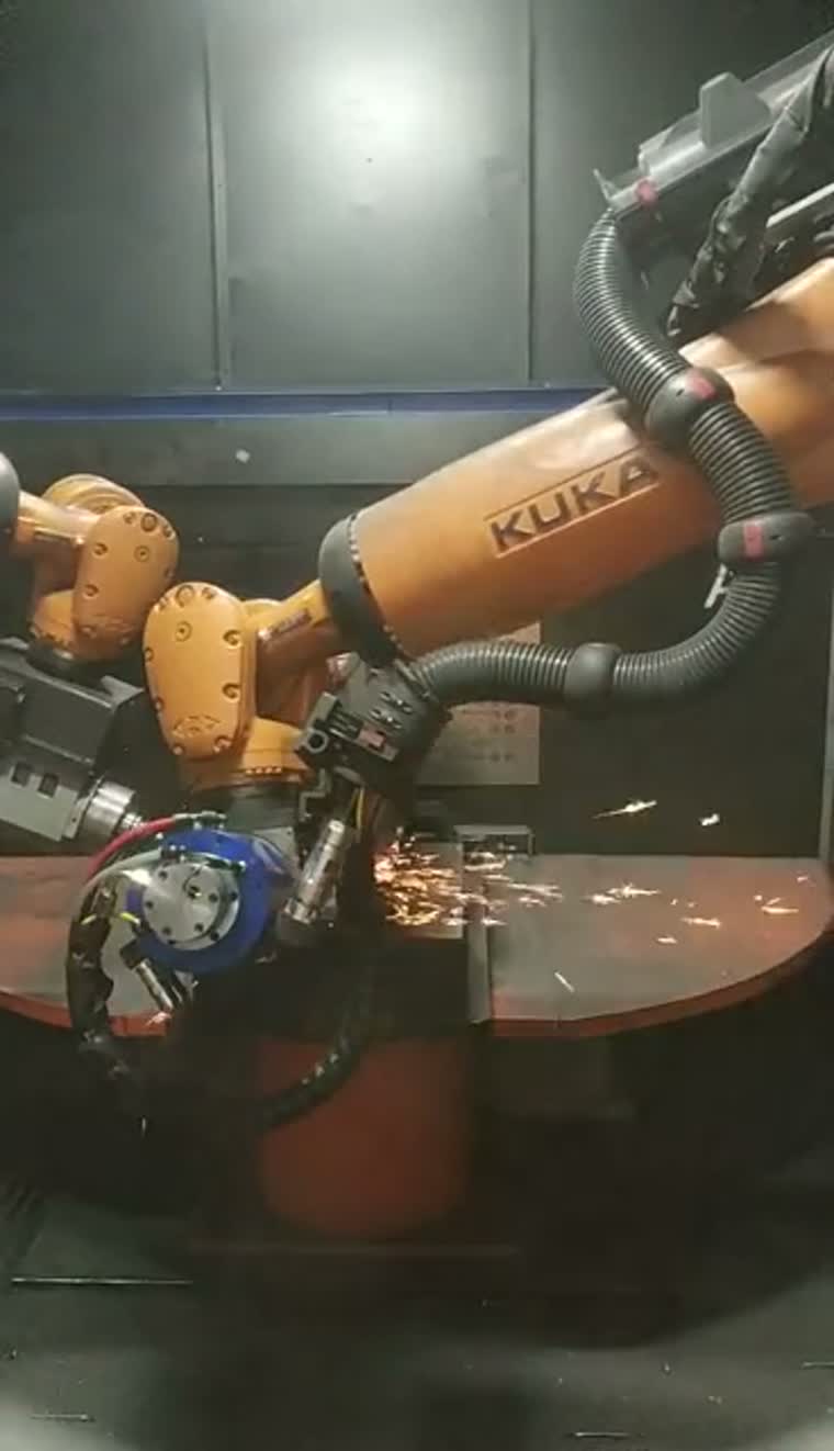
Start with the casting and its constraints
Typical workpiece families include engine blocks, cylinder heads, transmission housings and motor housings. Clamping access, turning clearance and the tool approach determine the cell layout.
Incoming castings can vary in contour and parting-line position. Review representative castings, fixture datums and the areas to be processed before selecting the handling route.
Maximum workpiece mass: on request.
Maximum workpiece dimensions and turning envelope: on request.
A tool-held arrangement can suit workpieces that are difficult to carry through fixed finishing tools; the handling-route decision also depends on access and fixturing.
Cell layouts, force-control options and dust extractionCell configurations and tool access
Cell configurations combine a robot-held tool with a fixed fixture, a positioner or an alternating rotary table. Tool approach and access to the casting guide the arrangement.
Floating spindle options, automatic tool changing and a tool store can be specified around the required operations and the mix of workpieces.
Controlled contact-force range: on request.
Cell layouts, force-control options and dust extractionDie-cast housings
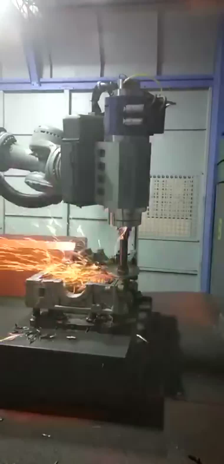
Deburring routes address flash, parting lines and gate remnants on cast housings; incoming variation and tool access shape the process.
Engines and powertrain
Engine blocks and cylinder heads can require different tools for external edges and side bores, with vision location and tool changes included where the process calls for them.
Automotive and motorcycle components
Cast component families can be evaluated for a robot cell or a dedicated machine, considering fixture commonality and how often the product changes.
Motor manufacturing
Motor-housing deburring is a typical application for robot and dedicated-machine integration, with the clamping datum and edge access defined for each housing family.
Robot cell vs special-purpose machine
| Workpiece family | Configuration | Axes and positions | Changeover flexibility | Production mix |
|---|---|---|---|---|
| Large cast housings | Robot cell | Articulated tool motion; fixed or positioned workpiece | Tool and fixture changes for different housings | Mixed families with varying features |
| Repeated cast component families | Special-purpose machine | Coordinated axes; single or alternating positions | Dedicated fixtures with planned changeovers | Repeated runs within a defined family |
| Small contoured components | Special-purpose machine | Coordinated axes and indexed positions | Tooling changes within the supported component range | Repeated contour-processing tasks |
| Medium and large components | Special-purpose machine | Linear or rotary-indexed arrangements | Part-specific fixtures and process setup | Defined processing sequences |
Scroll horizontally to compare all fields.
Special-purpose machines at the solution level
Special-purpose machines provide coordinated tool motion with single, alternating or indexed processing positions. They are evaluated at the solution level around the part family and fixture arrangement.
Example workpieces include phone housings, camera modules, set-top-box housings, door handles and automotive plastic components.
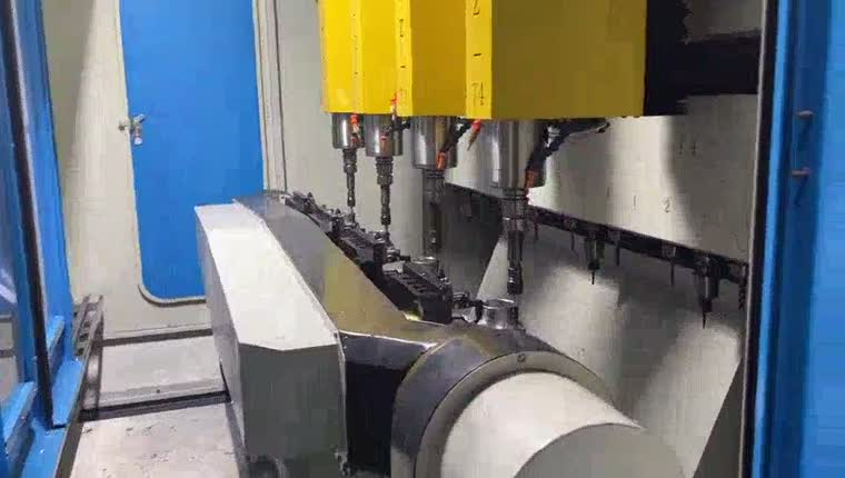
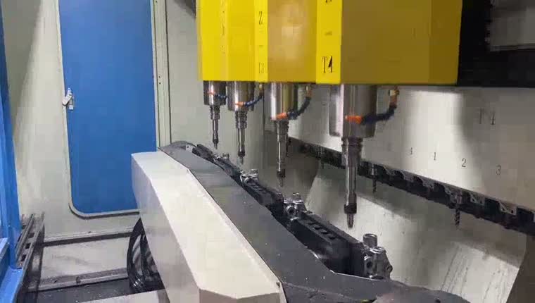
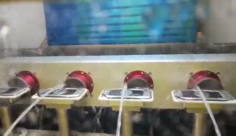
A wet-processing route is available for suitable contour-finishing tasks, using liquid around the tool and rotating fixtures. Suitability depends on the material and required finish.
For axle components, consider the transition from welding to deburring when planning the fixture and processing sequence.
Axle welding and post-weld processingEVST Scan-to-Path Grinding
EVST Scan-to-Path Grinding generates a grinding path from scanned workpiece contours within defined processing regions; it does not remove the need to define the process, validate fixtures or check the finished part.
For a programming free grinding robot, the intended reduction is manual point-by-point path teaching. Tool selection, scan coverage, process boundaries and acceptance criteria still need to be established.
Discuss your workpiece →From the scanned contour to execution
Scan the workpiece, identify the contour within the defined processing region, and generate a path for robot execution. The path must be checked against fixture access and the selected tool.
Capture the workpiece contour in the selected region.
Identify the processing edge and generate the tool path.
Execute the checked path with the selected contact tool.
Concept diagram · Steps require workpiece and cell validation.
Force-controlled execution supports contact during the generated path; force-control options and their specifications are selected with the wider cell configuration.
Cell layouts, force-control options and dust extractionThree-dimensional vision and adaptive paths
Three-dimensional imaging and processing can build a workpiece representation and adapt the path to spatial variation. CAD-free processing is optional where the contour and process can be established from the scan; product inspection is also optional.
Scan duration under the agreed coverage and test conditions: on request.
Scanning accuracy under the agreed material, geometry and test conditions: on request.
Laser detection and deviation compensation
Point-laser detection can compare the current part with the preceding part and compensate for positional variation at a parting line. This comparison concerns part-to-part deviation, rather than deviation from a CAD model.
Laser measurement of weld protrusion can inform position compensation and coordinate with the finishing tool during weld-bead processing. The measurement and removal strategy must be matched to the joint.
Offline programming and simulation
Offline programming prepares the robot path away from the cell. Collision checking and code simulation support review before a postprocessor produces the controller-specific program.
Define the tool, fixture and robot path.
Review collisions and simulate the program.
Output controller code, then validate on the cell.
Concept diagram · Steps require workpiece and cell validation.
Simulation supports preparation; the robot program, tool geometry and fixtures still require validation on the actual cell.
Post-weld and weld-bead grinding
Robotic weld seam grinding can use a robot-held finishing head around an aluminum frame. The fixture supports access to the weld bead while the tool follows the selected removal path.
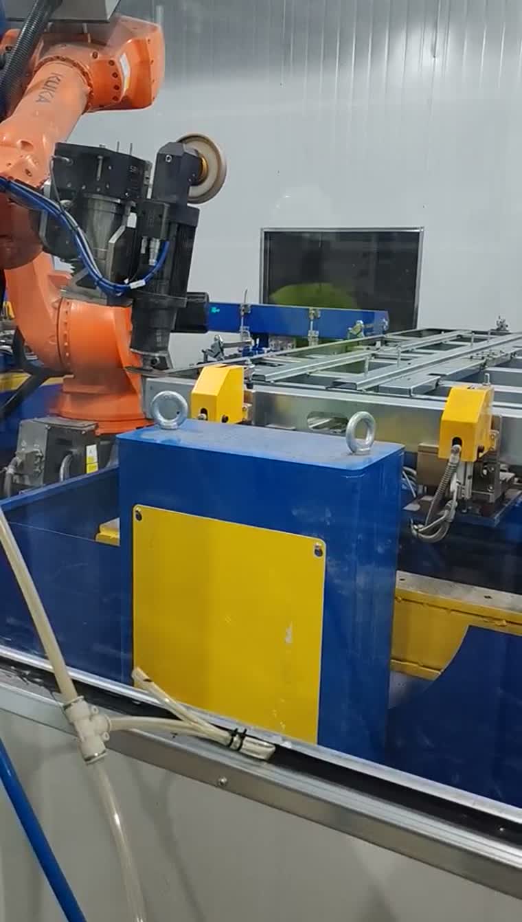
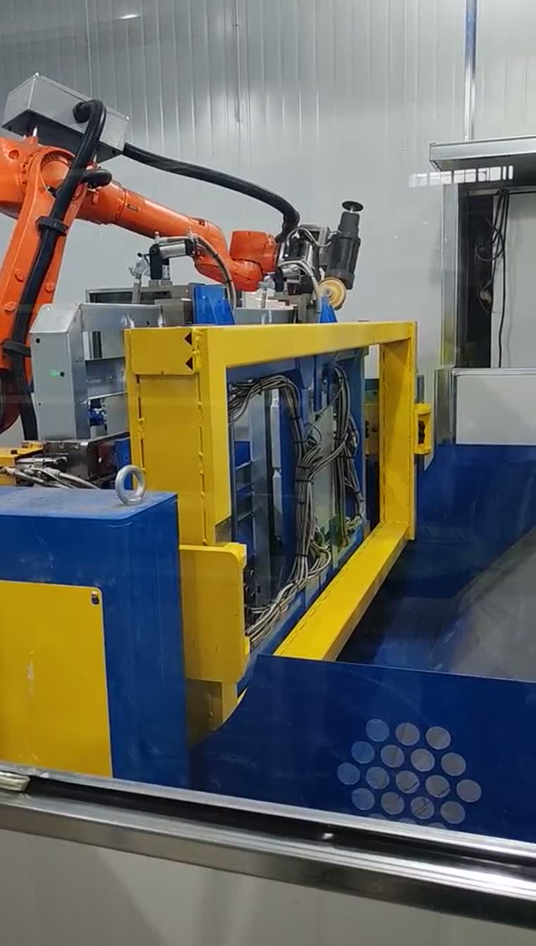
Battery-tray friction-stir-weld finishing is a related process with its own fixture and process requirements.
Battery-tray finishing and related process optionsTypical applications and integration scope
Typical applications include cast-housing edge cleanup, engine-component deburring and frame weld-bead finishing. Delivery scope is defined around fixtures, tools, robot integration and process validation.
Loading and unloading interfaces are defined with the upstream and downstream equipment.
Share representative workpieces, the edges or welds to be processed, fixture datums and the acceptance criteria to start a configuration review.
Questions before selecting a deburring cell
What does "programming-free" actually mean — no teaching, or no CAD model?
It means generating the process path from detected contours to reduce point-by-point teaching. Working without a product CAD model is an optional configuration; fixtures, tools and process acceptance still need validation.
How is the tool path generated when the casting varies from part to part?
The scan identifies the relevant contour within a defined processing region. Path generation uses that contour, while a suitable detection arrangement can compensate for part-to-part variation. Out-of-scope geometry requires a process review.
When does a special-purpose deburring machine beat a robot cell?
A dedicated machine is worth evaluating when part families, fixtures and processing sequences repeat. A robot cell can be evaluated when access, tool approach or the product mix calls for a different arrangement; compare them on the actual workpieces.
Can deburring and post-weld grinding run in the same cell?
They can be considered within a shared concept if fixtures, tool access and process requirements are compatible. Combining them is a project decision, not a standard capability assumed for every layout.
What tool changing is needed for mixed-model production?
Define the operations and required tools for each part family first. Automatic tool changing and a tool store can then be configured around that mix, including access and fixture-clearance checks.
Can vision path generation be retrofitted to an existing cell?
Retrofit suitability is assessed case by case. Check robot-controller interfaces, scan access, calibration, tool geometry and fixture compatibility before defining the upgrade; a scan demonstration alone does not establish cell compatibility.