
Review a rotating weldment with both the loaded fixture’s swept space and the moving torch in the same layout. The useful question is whether the required relationship can be maintained through the movement, including approach and withdrawal. Reaching the weld start point does not establish clearance later in the rotation or demonstrate an acceptable joint.
Follow the complete loaded shape
At 00:04, the opening scene shows the robot torch near a tubular workpiece supported by a turning arrangement. At 00:14, the video presents a different, larger circular workpiece. They are separate examples; the edit does not establish a shared fixture setup or one continuous manufacturing cycle.
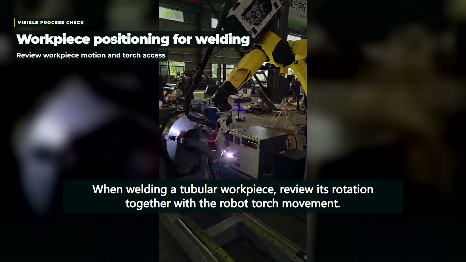
For a proposed layout, add projecting ends, brackets, clamps, and attached services to the workpiece outline. Then consider the space occupied as the assembly turns. A seam can remain near the intended working area while another part of the loaded assembly approaches a pedestal, support, or service line. The layout review should account for that outer geometry.
Put loading limits beside geometry
A positioner-tooling design note addresses weight, inertia, center of gravity, and the turning envelope for its specified equipment. These are conditions for that product context, not universal numerical limits and not identification of the positioner in this footage.
For the actual unit being considered, use its applicable documentation and loading assessment. If tooling or a tabletop is changed, retain the details needed to assess the modification. A load described only by its mass leaves the evaluator without its distribution and geometry.
| Review object | Include in the proposed model | Do not infer from the video |
|---|---|---|
| Loaded fixture | Workpiece, clamps, support, and attached utilities | Approved loading or stopping behavior |
| Torch route | Torch body, required orientation, and service lines | A validated continuous clearance path |
| Weld joint | Joint location and the required welding conditions | Strength, internal quality, or acceptance |
Coordination needs its own evidence
The robotic arc-welding overview explains how workpiece manipulators can extend access and how their control may be integrated with the robot. This is background on system arrangements. The observed simultaneous or sequential motion does not reveal the filmed control architecture, sensing functions, or process settings.
A project review can therefore keep geometry and control confirmation as separate tasks. First document the positions and transitions the process requires. Then obtain evidence that the selected arrangement can execute them under the specified conditions. Where a different workpiece is introduced, establish its own fixture and movement assessment rather than transferring the first workpiece’s conclusions.
The existing positioner-cell planning article addresses a broader set of setup and recovery questions. The present review concentrates on what belongs inside the two moving envelopes: loaded workholding and torch equipment.
Keep joint acceptance outside the motion demonstration
A smooth movement and visible welding activity do not provide inspection of the finished joint. Materials, joint preparation, process conditions, and the applicable inspection requirements remain necessary inputs. The recorded views also cannot confirm that protection against motion, arc exposure, fumes, or intervention hazards has been validated.
For a technical discussion, a joint drawing is most useful when accompanied by the complete loaded fixture layout and the proposed movement range. The combination makes it possible to distinguish a torch-access question from a loading question, while reserving weld quality for the tests that can actually establish it.