
Direct answer: Battery tray robotic welding should lock the fixture datum before the seam program is optimized. EVST checks the tray supports and clamps, divides the perimeter and internal joints into zones, verifies the complete torch and cable envelope, and requires a clear retreat before each side change. Welding parameters, distortion and quality remain measured acceptance questions.
Who this is for: Battery-system manufacturing engineers and automation buyers planning robotic welding around a large tray perimeter and its internal seam zones.
Scope: This guide uses footage of a battery tray held around its perimeter while a robot approaches, follows visible seams and retreats before changing sides. It covers datum, access and sequence decisions; it does not prove welding parameters, distortion, cycle time or acceptance quality.
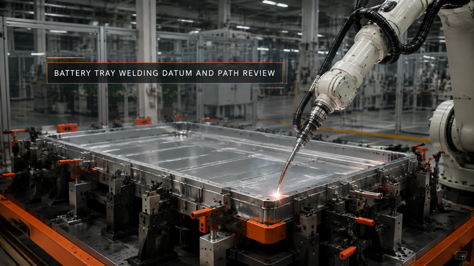
Why battery tray robotic welding begins with a fixture state
The first engineering question is not how quickly a robot can trace a programmed line. It is whether every tray arrives in a repeatable relationship to the robot frame. The reviewed footage shows the workpiece supported and restrained around its perimeter, followed by distinct robot approaches to visible joints. That observation supports a datum-and-access discussion, not a claim about the resulting weld.
A tray is a broad assembly with several references acting at once: locating features establish position, supports carry the presented shape, and clamps hold a declared state while the torch moves. If those functions are not separated in the fixture design, a program may repeat perfectly while the joint moves relative to it. In practice, the review records which features locate, which support and which restrain, then checks whether loading and release preserve that definition.
According to ISO 13920:1996, dimensional and geometrical tolerances for welded constructions belong to a declared acceptance framework. The standard does not turn a visible clamp into proof of accuracy. The project still needs a drawing-based datum scheme, measurement points and acceptance values tied to the tray state before and after welding.
Battery tray robotic welding is a fixture-and-path problem before it is a speed problem. A stable tray datum fixes every seam relative to the robot; the complete torch, wrist and cable envelope must then clear the perimeter, corners, internal joints and every retreat. Each side change is a new approach case because clamp positions and service routing can alter the available posture. Video can show that the robot follows a visible route, but it cannot establish heat input, distortion, cycle time or weld acceptance. Those conclusions require a qualified procedure, declared restraint states, representative trays, dimensional measurement and the specified inspection record. Keeping motion evidence separate from process acceptance makes the selection review reproducible when tray geometry, clamping or seam order changes.
Divide the tray into access zones before programming
The visible seams do not form one interchangeable loop. Straight perimeter runs, corners, internal joints and terminal regions ask for different tool orientations and leave different space for the wrist and services. A useful seam map therefore identifies each zone, its required travel direction, the fixture elements beside it and the permitted approach side.
This zone map is where automatic welding system solutions become concrete. It connects the workpiece drawing to robot poses instead of treating the cell as a generic reach sphere. The footage includes an initial approach, travel along an edge and later work in another seam area; it does not establish that every joint was welded in one continuous cycle.
The design review should also mark joints that cannot share the same fixture state. If one clamp must move, or if access changes after another joint is completed, that condition becomes an explicit state transition. Hiding it inside a long program makes recovery harder to diagnose and acceptance evidence harder to trace.
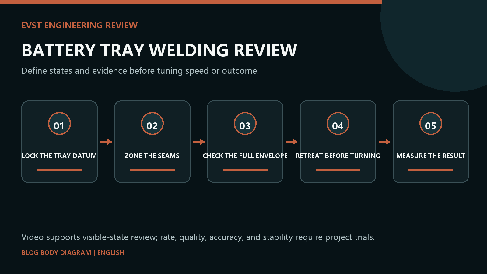
Check the complete torch envelope at corners and endpoints
A reachable start point proves very little on a battery tray. The torch neck, wrist, mounting bracket and cable pack continue moving after the tool centre point reaches the joint. Corners can consume wrist margin, and the last part of an edge can bring services closer to the tray wall or perimeter clamp than the first part did.
A large workpiece pose and reach test should therefore sample the complete route, including the approach and retreat. The relevant evidence is not only a simulated green point. It is a collision review with the actual tool stack, declared cable routing, clamp states and robot posture at the most constrained corner, endpoint and internal-joint transition.
According to ISO 10218-2:2025, safety is assessed for the industrial robot application and cell rather than the bare robot alone. For this task, guarding, fixtures, access for loading and every commanded or recovery movement belong in the same assessment boundary.
Make every side change a named transition
The footage shows the robot withdrawing from one region before approaching another. That sequence is valuable because a side change should not be an unexamined sweep across the tray. A named transition defines the last safe pose in the current zone, a clear corridor and the first verified pose for the next joint family.
The same logic applies after an interruption. Welding and cutting path boundaries should state where a restart is permitted, which fixture state is expected and how the torch returns without crossing the workpiece or a clamp. According to ISO 12100:2010, limits and foreseeable operating situations are inputs to risk reduction; normal production is not the only state that needs a path.
| Observed condition | Engineering decision | Evidence needed |
|---|---|---|
| Stable datum; open perimeter | Program by seam zone | Fixture state and complete path review |
| Corner or terminal has low clearance | Change posture or access direction | Actual torch, wrist and cable envelope |
| Clamp state changes between joints | Create a named transition | State sequence and restart test |
| Distortion limit is critical | Plan restraint, sequence and measurement | Procedure qualification and dimensional records |
Keep welding procedure decisions separate from motion
Robot motion can be reviewed from the footage; heat input, filler delivery and joint quality cannot. The seam order may influence distortion, but choosing that order requires the tray material, joint design, fixture restraint, process specification and a way to measure the finished assembly. A smooth path is not a substitute for those inputs.
According to ISO 3834-1:2021, quality requirements for fusion welding are selected within a broader quality system. For a battery tray robotic welding project, that means the program is linked to the applicable procedure, traceable fixture state and inspection plan. It does not mean the cited standard supplies a tray-specific parameter set.
Where distortion is a buying concern, the acceptance plan should distinguish reference measurements, in-process observations and final dimensional checks. The plan can then reveal whether a change came from loading, restraint, thermal sequence or release instead of assigning every deviation to robot path accuracy.
Close the review with evidence the camera cannot provide
The recorded scene confirms a large tray, perimeter restraint, several torch approaches, visible travel and withdrawal between regions. It does not show the drawing tolerance, qualified welding procedure, parameter log, dimensional result, penetration, defect level, production cycle or recovery test. Those remain open requirements rather than implied successes.
EVST therefore closes the application review with a traceable chain: declared datum and fixture states, seam-zone ownership, complete tool-envelope checks, transition and recovery logic, procedure records and measured acceptance. If tray geometry, clamp sequence, tool stack or joint list changes, the affected links are reviewed again instead of assuming the original program still proves them.
Frequently asked questions
Why does the tray datum come before the robot path?
Every programmed seam assumes a stable relationship among the tray, fixture and robot frame.
Does a reachable arc start validate a tray seam?
No. The torch, wrist and cable pack must clear the complete seam and retreat.
Can footage prove distortion control?
No. Distortion needs a defined welding procedure, restraint plan and dimensional measurements.
When should a side change occur?
After the robot has left the active seam zone and the next approach has been verified.
Project inputs for an application review
A battery tray application review starts with the physical references and acceptance evidence that define every seam zone.
- Tray drawing, material and mass properties
- Datum scheme, support points and clamp sequence
- Complete seam map and required torch directions
- Side-change, retreat and recovery states
- Welding procedure, dimensional and inspection criteria
Send those project inputs to EVST for an evidence-led review of battery tray fixturing, path access and validation scope. Related reading: welding and cutting path boundaries.