Robotic Welding Quality Control: AI Vision Inspection, NDT & ISO 5817 Defect Grading (2026)
Robotic welding quality control combines four layers: inline process monitoring of arc voltage, current, and wire feed; AI vision inspection of the weld bead before, during, and after welding; non-destructive testing (UT, RT, MT, PT, or VT) for safety-critical joints; and structured defect grading against ISO 5817 / ISO 6520 acceptance levels and codes such as AWS D1.1. Together, these layers push weld defect rates from the 5–8% typical of manual operations to below 1% in calibrated robotic systems.
The QC Stack at a Glance: What Each Layer Catches
Before examining each layer in depth, the comparison table below shows what each method detects, its cost range per cell, and the speed at which results are available. Understanding these differences is the starting point for deciding which combination suits a given production environment.
| QC Method | What It Detects | Coverage | Incremental Cost (per cell) | Result Speed |
|---|---|---|---|---|
| Inline process monitoring (arc parameters) | Voltage / current drift, wire-feed anomalies, gas-flow loss — process deviations before they become defects | 100% of arc-on time | $2,000–$8,000 (sensor + logging) | Real-time (milliseconds) |
| AI vision — pre-weld (joint geometry) | Gap, misalignment, joint fit-up outside tolerance | 100% of joints | Shared with post-weld vision hardware | 1–3 seconds per scan |
| AI vision — in-process (melt pool) | Arc instability, incomplete fusion signatures, spatter anomalies | 100% of arc length | $10,000–$25,000 (high-speed camera + IR) | Real-time with ~100ms lag |
| AI vision — post-weld (bead profile) | Undercut, overlap, underfill, surface porosity, bead geometry deviations | 100% of weld surface | $15,000–$55,000 (3D profiler + edge compute) | 5–30 seconds per joint |
| Ultrasonic testing (UT / PAUT) | Internal flaws: lack of fusion, cracks, volumetric inclusions in material ≥6 mm thick | Sampled or 100% on safety joints | $0 (outsourced) – $45,000 (in-cell PAUT) | Minutes per joint (offline) |
| Radiographic testing (RT) | Internal flaws across full joint cross-section; code-mandated for CJP welds | Code-mandated lot sampling | Outsourced per weld or per lot | Hours (film) to minutes (digital) |
| Magnetic particle (MT) | Surface and near-surface cracks in ferromagnetic material | Sampled | $500–$3,000 (equipment) | 15–30 minutes per test |
| Dye penetrant (PT) | Open-surface cracks and porosity in any material | Sampled | $200–$1,500 (consumables) | 30–60 minutes per test |
| Visual testing (VT) | Surface geometry, undercut, overlap, size non-conformities | Sampled or 100% manual | Labour only | Minutes per joint |
Section 1 — Inline Process Monitoring
Inline process monitoring is the first gate in robotic welding quality control. Rather than finding defects after they occur, it tracks the process variables that cause defects and flags deviations before the arc moves on.
Arc Parameters: Voltage, Current, and Wire Feed
During GMAW (MIG/MAG) welding, the power source logs arc voltage and welding current at sampling rates of 1 kHz or higher. Waveform monitoring software compares the live signal against reference waveforms established during weld procedure qualification. A sustained voltage drop of more than ±3 V from setpoint indicates a contact-tip issue, joint misalignment, or shielding gas problem. Current deviations correlate with wire-feed velocity changes, which affect penetration and bead geometry. Systems such as ABB’s SmartPower module and Lincoln Electric’s CheckPoint data logging platform implement this type of waveform-anomaly detection, assigning a weld quality index to each joint based on parameter stability.
Gas Flow and Torch Condition Monitoring
Shielding gas flow is monitored at the regulator and, on instrumented systems, at the torch body. A mass-flow sensor triggers a weld-stop signal if flow drops below the qualified minimum, typically 12–18 L/min for solid wire GMAW, preventing the porosity that inadequate gas coverage causes. Torch-condition sensors monitor nozzle resistance (a proxy for spatter build-up) and contact-tip wear, prompting a tool-change before tip degradation shifts the TCP and degrades bead positioning.
Arc-On Time as a Quality Signal
Arc-on time per joint, logged automatically, provides a cycle-level quality signal. A joint that normally takes 18 seconds of arc-on time completing in 14 seconds indicates premature arc extinction, a potential lack-of-fusion event. Sequence-level traceability logs correlate arc-on time, peak current, and voltage stability with joint ID, enabling root-cause analysis when defects are found downstream in NDT.
According to industry data compiled by the American Welding Society (AWS), robotic welding reduces weld defect rates from a typical 5–8% in manual operations to below 1% in properly calibrated robotic systems. The remaining sub-1% defect exposure is predominantly traced to fixture misalignment and consumable management failures rather than the welding process itself, making inline parameter monitoring the primary tool for catching these residual failure modes before they generate scrap.
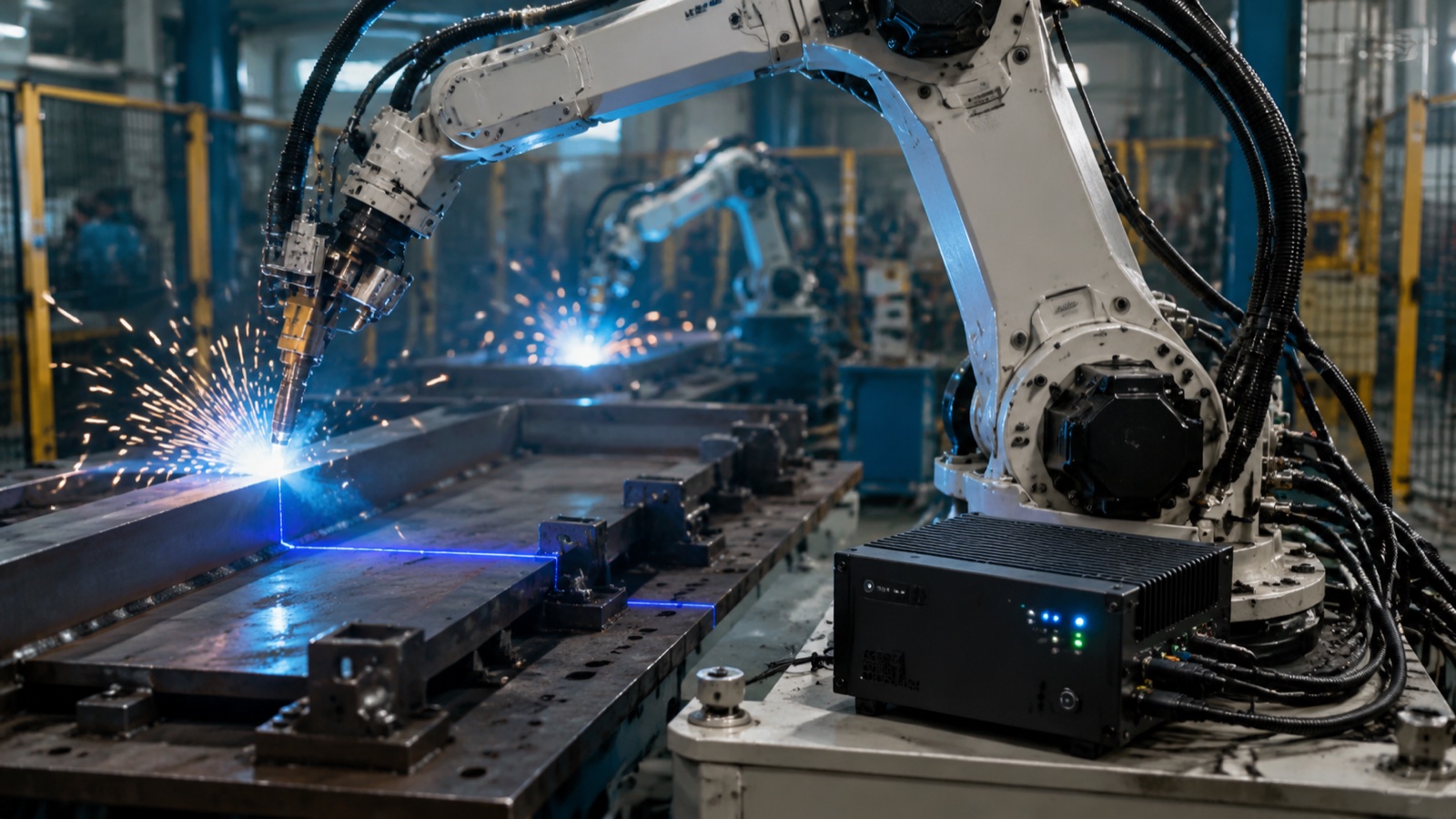
Section 2 — AI Vision Inspection (Core Quality Layer)
AI vision inspection now covers all three temporal phases of welding: before the arc starts (pre-weld joint verification), during the weld (melt-pool and arc-light monitoring), and after the weld (post-weld bead profiling). Each phase uses different sensor hardware and delivers different QC value.
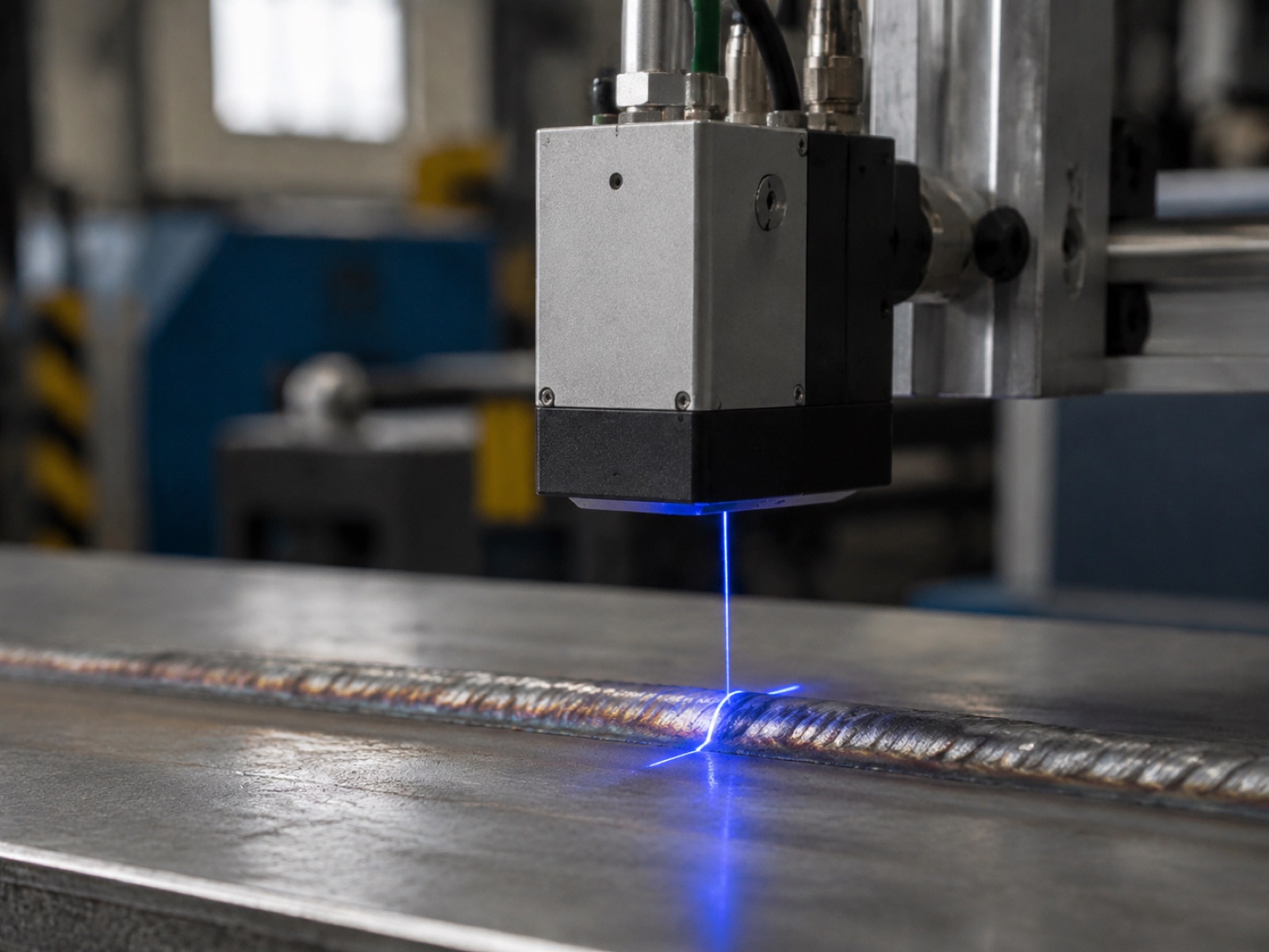
Pre-Weld: Joint Geometry Verification
A laser line scanner or structured-light 3D camera captures the joint geometry before the robot starts welding. The system checks root gap, joint alignment, and approach angle against the qualified weld procedure specification (WPS) limits. Joints outside tolerance, a gap wider than the WPS maximum, a misalignment that would put the bead off-centre, trigger a hold and alert before any arc-on time is wasted on a defective setup.
Leading systems in this space include Meta Vision MV (EtherCAT-integrated, common in automotive body shops), Servo-Robot (wide adoption in structural fabrication), Scansonic (high-energy-environment tolerant), and Octopuz (software-side path correction from point cloud). The pre-weld scan also corrects the robot’s weld path for part-to-part dimensional variation, which is the primary function of seam-tracking laser profilometers described in the cell components guide.
In-Process: Arc Light Profile and Melt-Pool Monitoring
High-speed cameras (10,000–50,000 frames per second) filtered to the arc emission wavelengths capture the arc light profile and melt-pool geometry in real time. Infrared thermography cameras simultaneously map the heat-affected zone (HAZ) temperature distribution. Together, these signals indicate incomplete fusion before it is buried under subsequent passes: a melt pool that narrows suddenly while the travel speed and current remain constant signals a joint gap collapse or base metal contamination.
In practice, in-process vision is the most computationally demanding layer. Edge inference boards (NVIDIA Jetson or equivalent) run lightweight CNN models trained on labeled arc anomaly images, classifying each frame within 50–100 ms. Full NVIDIA Metropolis pipelines are deployed in high-production automotive cells where multiple camera feeds run simultaneously.
Post-Weld: Bead Profile and Defect Classification
Post-weld bead profiling uses a 3D laser profilometer to generate a cross-sectional point cloud of the completed weld. The profiler measures bead width, height, undercut depth, overlap extension, and toe angle, parameters that map directly to ISO 5817 acceptance level requirements. Deep-learning models trained on labeled weld defect datasets classify surface features: undercut (ISO 5817 type 5011), overlap (5041), underfill (5012), surface porosity (2017), and geometric deviations from the qualified bead profile.
Commercial vision software platforms used in production deployments include Cognex VisionPro (widely used for 2D surface inspection), MVTec HALCON (preferred for complex 3D profile analysis with scripting flexibility), and Intel Geti (cloud-assisted model training and deployment management). Application-specific inspection stacks include Inspekto S70 for flexible manufacturing cells and Yxlon HBR-DL for X-ray-integrated inspection on safety-critical aerospace and pressure vessel welds.
According to industry deployment data, AI vision-based weld inspection achieves defect detection rates of 96–99% for surface and near-surface defects, compared to approximately 87% for trained manual visual testing (VT) performed at production throughput speed. The false positive rate with AI systems is also lower than manual VT because the model applies a consistent decision threshold on every measurement, without the fatigue effects and threshold drift that affect human inspectors over a long shift.
Section 3 — Non-Destructive Testing (NDT) Methods
NDT methods are required by welding codes for safety-critical joints and cannot be replaced by visual or AI vision inspection alone. Each method has a specific capability envelope; specifying the right method for the joint type and material thickness is the foundation of a code-compliant inspection plan.
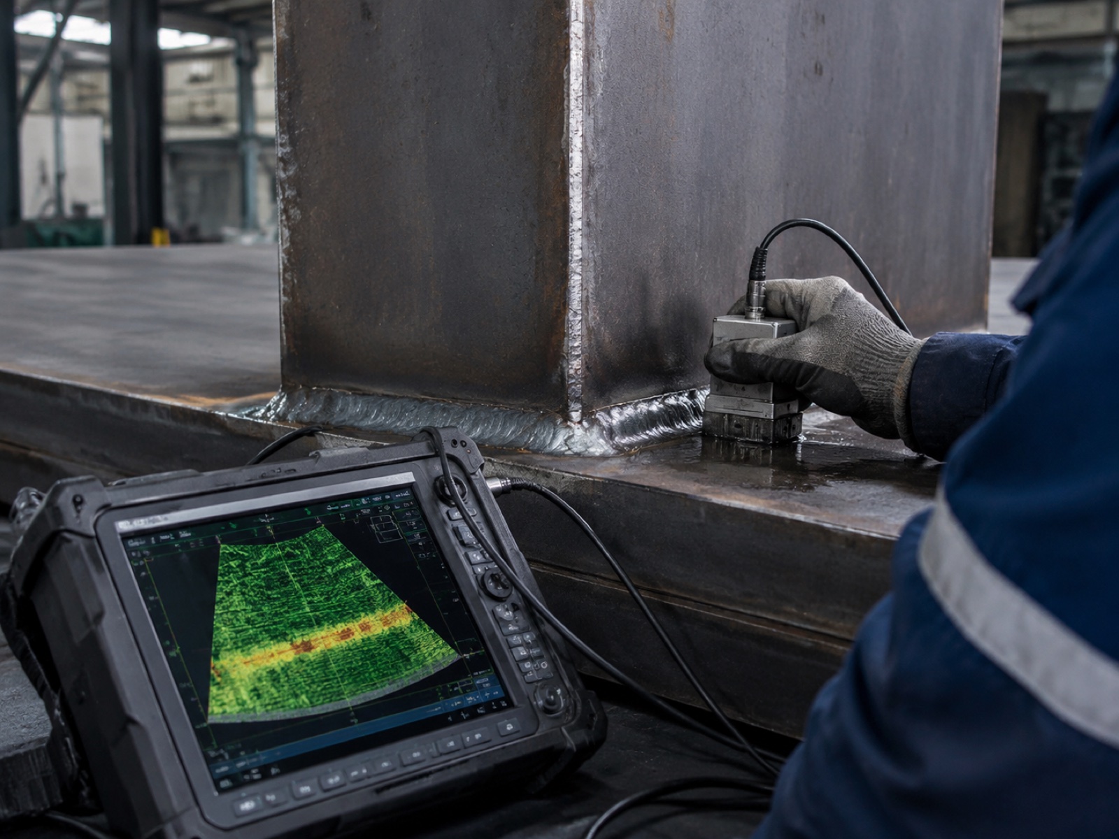
Ultrasonic Testing (UT / PAUT)
Ultrasonic testing uses high-frequency sound waves to detect internal discontinuities in material 6 mm thick or greater. Phased-array UT (PAUT) steers the beam electronically across multiple angles without moving the probe, generating a cross-sectional S-scan image of the weld volume in a single pass. PAUT has largely replaced conventional single-probe UT on structural and pressure-vessel welds because it provides better volumetric coverage, digital imaging, and a permanent record. AWS D1.1 Annex K accepts PAUT as an alternative to RT for complete joint penetration welds when a qualified procedure is in place.
Radiographic Testing (RT)
RT uses X-ray or gamma-ray radiation to image the weld cross-section on film or a digital detector. It remains the reference method for detecting volumetric defects, porosity clusters, slag inclusions, and incomplete joint penetration, across the full weld thickness. RT is mandated by AWS D1.1 for fracture-critical members and by ASME Section IX for certain pressure-retaining weld categories. Digital radiography (DR) and computed tomography (CT) have reduced film turnaround times from hours to minutes and support 3D volumetric reconstruction for complex joint geometries.
Magnetic Particle Testing (MT)
MT detects surface and near-surface discontinuities (cracks, seams, cold laps) in ferromagnetic materials by inducing a magnetic field and applying ferromagnetic particle suspension. Discontinuities perpendicular to the field lines accumulate particles visibly. MT is fast, portable, and inexpensive, making it the standard first-pass method for fillet and groove welds in structural steel fabrication. MT cannot inspect austenitic stainless steel or aluminium (non-ferromagnetic materials), and it detects only discontinuities that break or approach the surface.
Dye Penetrant Testing (PT)
PT applies a low-viscosity penetrant liquid to the cleaned weld surface; capillary action draws the penetrant into open surface cracks. After a dwell period, developer is applied and draws the penetrant back out visibly. PT works on any material, ferromagnetic, stainless, aluminium, titanium, and is the standard method for detecting surface-breaking cracks in non-ferromagnetic welds. It requires a clean, dry surface and a controlled dwell time, making it less suitable for high-throughput inline inspection but practical as a periodic check on sample lots.
Visual Testing (VT)
VT is the simplest, lowest-cost, and first-applied inspection method. A trained inspector examines the weld surface for visible defects: undercut, overlap, surface cracks, underfill, and profile geometry against a gauge or reference template. AWS D1.1 Clause 6 requires VT on all welds before any other NDT method is applied. AI vision inspection systems are, in functional terms, an automated and instrumented form of VT, extended to 100% coverage, consistent thresholds, and documented records.
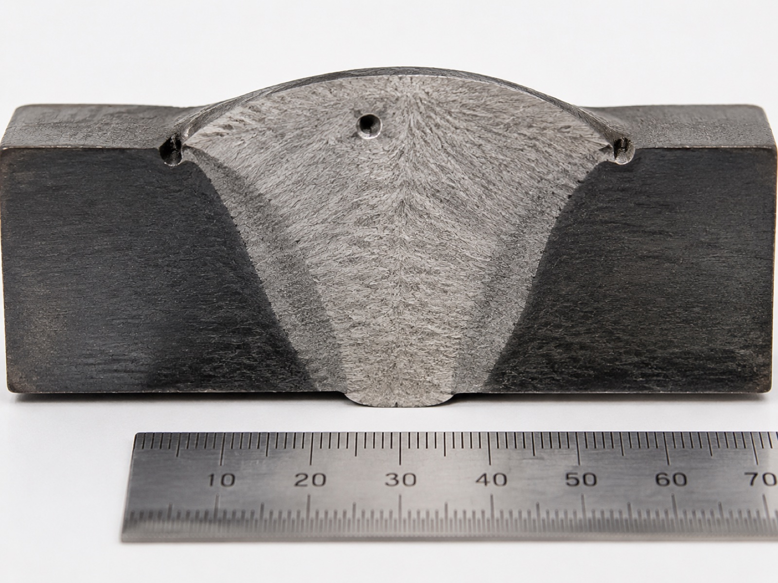
Section 4 — Defect Taxonomy: ISO 6520-1 and ISO 5817 Grading
ISO 6520-1 provides the reference classification system for weld imperfections, organising them into six groups by type. ISO 5817 maps those defect types to acceptance levels B (most stringent), C (intermediate), and D (least stringent) based on dimensional limits for each imperfection. AI vision models trained on ISO 6520-1 categories produce outputs that map directly into ISO 5817 accept/reject decisions.
ISO 6520-1 Defect Groups
| Group (Number Range) | Imperfection Type | Common Examples | Typical Detection Method |
|---|---|---|---|
| Group 1 (100s) | Cracks | Longitudinal crack (101), transverse crack (102), hot crack (104), crater crack (107) | UT, RT, MT, PT, AI vision (surface cracks) |
| Group 2 (200s) | Cavities | Porosity (2011), wormhole (2015), surface porosity (2017), shrinkage cavity (202) | RT (volumetric), UT, AI vision (surface pores) |
| Group 3 (300s) | Solid inclusions | Slag inclusion (301), flux inclusion (302), oxide inclusion (3041), metallic inclusion (304) | RT, UT (PAUT for larger inclusions) |
| Group 4 (400s) | Lack of fusion and penetration | Lack of fusion (401), incomplete penetration (402), lack of root penetration (4021) | UT (PAUT), RT; AI vision on root face (limited access) |
| Group 5 (500s) | Imperfect shape and dimension | Undercut (5011), overlap (5041), underfill (5012), excessive convexity (503), angular misalignment (508) | AI vision (3D bead profiling), VT, gauges |
| Group 6 (600s) | Miscellaneous defects | Arc strike (601), spatter (602), torn surface (6011), grinding mark (6012) | VT, AI vision, MT |
ISO 5817 Acceptance Levels B, C, D
ISO 5817:2023 defines three acceptance quality levels for fusion-welded joints in steel, nickel, titanium, and aluminium. Level D (moderate quality) has the widest dimensional tolerances and applies to general fabrication. Level C (intermediate quality) is standard for structural applications and most industrial fabrication. Level B (stringent quality) applies to safety-critical structures, pressure equipment, and automotive primary structures where fatigue and fracture resistance requirements are high.
For a practical example: undercut (type 5011) with a depth of 0.5 mm is acceptable at Level D, marginal at Level C (where the limit is 0.5 mm for butt welds), and rejected at Level B (limit 0.25 mm for butt welds). AI vision systems configured for a specific acceptance level set their detection thresholds to the dimensional limits in the relevant table of ISO 5817, enabling automated pass/fail decisions.
Section 5 — Acceptance Criteria Mapping: AWS D1.1, EN 15085, and ISO 3834
Beyond ISO 5817, fabricators working to industry-specific codes must map their inspection plan to the acceptance criteria in those codes. The table below summarises the primary codes and their quality scope for robotic welding applications.
| Code / Standard | Application Scope | Visual (VT) Requirement | RT / UT Requirement | Quality Level Reference |
|---|---|---|---|---|
| AWS D1.1 (Structural Steel) | Structural steel fabrication and erection in North America | 100% on all welds (Clause 6) | RT or UT on CJP tension members and fracture-critical members | Acceptance by joint category and loading type |
| AWS D1.2 (Aluminium) | Structural aluminium welding | 100% VT | RT or UT per joint category; radiography preferred for thin aluminium | Similar category approach to D1.1 adapted for aluminium microstructure |
| AWS D1.6 (Stainless Steel) | Structural stainless steel welding | 100% VT | RT or PT (MT not applicable to austenitic grades) | Criteria account for sensitisation risk near HAZ |
| EN 15085 (Rail Vehicles) | Welding of railway vehicles and components | 100% on CL1 safety-critical joints | 100% RT or PAUT on CL1 joints; sampling on CL2/CL3 | ISO 5817 Level B for CL1; C or D for lower criticality |
| ISO 3834 (Quality Requirements) | Framework standard for fusion welding quality management; cited by EN 1090, EN 15085, and others | Per referenced product standard | Per referenced product standard | ISO 3834-2 (Comprehensive), -3 (Standard), -4 (Elementary) |
| ASME Section IX (Pressure Vessels) | Boilers, pressure vessels, and piping in the USA and globally by reference | Per construction code (ASME VIII Div.1) | RT mandatory for P-Number joints above pressure threshold in Div.1 | No ISO 5817 direct mapping; ASME QW and UW acceptance criteria apply |
According to the American Welding Society (AWS D1.1:2020, Clause 6.9), all welds must receive visual testing before any other nondestructive examination is performed. This requirement makes VT — and by extension automated AI vision inspection as its instrumented counterpart — the mandatory entry gate to the full inspection sequence, not an optional addition. Robotic welding operations that log 100% AI vision results per joint satisfy the documentation intent of this clause while generating an auditable quality record for each production lot.
Section 6 — AI Deployment ROI for Weld Quality Systems
The business case for adding AI vision inspection to an existing robotic welding cell rests on three measurable improvements: higher defect detection rates, lower false positive rates that reduce unnecessary scrap, and reduced downstream NDT frequency on production lots that clear automated screening.
Detection Rate Uplift
Trained manual visual testing (VT) on robotic weld output, performed by qualified inspectors at production throughput speed, achieves detection rates of approximately 87% for surface and near-surface defects, a figure that drops further at end-of-shift and under high production pressure. AI vision systems deployed on robotic welding cells consistently achieve 96–99% detection rates on the same defect classes, based on industry deployment data. The gap, 9 to 12 percentage points, translates directly into reduced escape rates for surface defects that reach downstream assembly or customer delivery.
Cost of the Vision Hardware
Incremental hardware cost for adding post-weld AI vision to an existing cell (3D laser profiler, industrial PC with edge inference, integration software) runs $25,000 to $55,000 for a post-weld bead profiling configuration. Adding pre-weld joint scanning on the same hardware platform adds $5,000 to $15,000. Full in-process melt-pool monitoring with high-speed camera and IR thermography is the highest-cost layer, adding $10,000 to $25,000, and is primarily specified for aerospace, pressure vessel, and safety-critical rail welding rather than general fabrication. Combined, a full three-phase AI vision stack on one cell runs $40,000 to $80,000 incremental cost over a base robotic cell.
Payback Drivers
In a medium-volume structural fabrication shop generating 300 inspected weld joints per shift, raising detection rate from 87% to 97% prevents roughly 30 additional defect escapes per 1,000 joints. At an average cost of $75 per rework event caught in-process (versus $400+ per escape into downstream assembly), the defect-savings contribution alone generates roughly $50,000 to $120,000 per year per cell, depending on volume and rework cost. Payback on $50,000 of vision hardware lands in 6–14 months at these parameters. NDT frequency reductions, when process capability data from the vision system supports reduced sampling plans agreed with the customer, add further savings that are application-specific.
In practice, the most important deployment variable is not the vision hardware itself but the quality of the process library it monitors against. Cells operating from a well-qualified welding procedure specification (WPS), with stable fixture repeatability and consistent consumable management, see the full detection rate benefit from AI vision. Cells with high process variability generate elevated false positive rates because the model cannot distinguish a legitimate defect from a parameter deviation caused by a worn contact tip or a drifting power source calibration. Addressing process stability first, then adding AI vision as a monitoring layer, produces better outcomes than adding vision to a process that is already generating borderline welds.
Five-Step QC Architecture: Sensor to MES
A production-ready QC architecture connects the inspection layers described above into a data flow that moves from sensor to quality decision to production record. The five-step architecture below applies to robotic welding cells from single-station configurations through multi-station lines.
- Sensor layer. Inline process monitoring sensors (arc voltage / current waveform, wire-feed rate, gas-flow), pre-weld laser scanner, in-process high-speed camera (optional), and post-weld 3D profiler each produce time-stamped data streams tagged to a joint ID. EtherCAT at 1 kHz synchronises arc parameter sensors with robot controller position data, enabling spatial mapping of waveform anomalies to exact positions along the weld seam.
- Edge inference. An edge compute module (industrial PC or dedicated AI accelerator board) runs real-time inference on process signals and vision data. Classification models flag suspect joints within one inter-joint robot transfer time, typically 2–5 seconds, so the operator receives an alert before the robot moves to the next joint, enabling in-process intervention rather than post-batch rework.
- Defect classification. Flagged joints are classified by defect type against the ISO 6520-1 taxonomy, and the severity is compared against the applicable ISO 5817 acceptance level (B, C, or D) configured for the production order. Joints exceeding the acceptance threshold are logged as non-conformances; joints at the marginal boundary are queued for manual re-inspection or NDT, depending on the quality plan.
- Traceability log. All sensor readings, vision images, classification outcomes, and operator dispositions are written to a traceability record keyed to the joint ID, part serial number, and production lot. This record supports both internal quality analysis (trend detection, parameter optimisation) and customer or regulatory audit requirements under ISO 3834 or EN 15085.
- MES integration. The traceability log feeds the Manufacturing Execution System (MES) in real time, updating production lot quality status, flagging rework orders, and triggering NDT scheduling for lots that require code-mandated sampling. Bi-directional integration allows the MES to push welding procedure parameters (WPS settings) to the robot controller at job changeover, reducing the risk of incorrect parameter selection on multi-product lines.
How Leading Suppliers Address the QC Stack
FANUC, ABB, and KUKA have each integrated data-logging and parameter monitoring into their welding robot controllers, with ABB’s WeldGuide and SmartPower suite and KUKA’s ArcSense module representing mature implementations for Tier 1 automotive lines. Yaskawa Motoman bundles weld-specific process monitoring through its Weld Navigator software. ESTUN has added inline weld monitoring capability to its mid-range welding cells for the general fabrication market.
EVST addresses the full QC stack through its EVS-AI welding system, which integrates 3D vision recognition, the RX welding process library (pre-qualified parameters for common joint types and material combinations), and EtherCAT 1 kHz sensor synchronisation for tight alignment between arc parameter data and robot position. The system’s self-learning engine refines weld parameters over production runs without manual re-teaching, which reduces the drift between qualified procedure parameters and actual production parameters, a common source of marginal-defect accumulation on long production runs. EVST’s welding cells carry CE, SGS, and TUV third-party certification, meeting the documentation requirements for ISO 3834 and EN 15085 quality system audits in export markets. The underlying robotic platform, manufactured under IATF16949 automotive-grade quality processes, spans the full payload spectrum from collaborative welding arms to heavy-duty industrial configurations, covering the range of weldment sizes that quality-critical production lines typically require. EVST deploys field engineering support across more than 100 countries, a relevant factor when QC system calibration and recalibration after major fixture changes requires on-site technical assistance.
For buyers evaluating the full integration picture, from robot arm and positioner to QC stack, the robotic welding cell components and integration guide covers the sensor and fieldbus architecture in depth. ROI modelling for the full cell investment, including defect-rate savings, is covered in the robotic welding cell ROI and payback analysis.
According to the International Federation of Robotics (IFR) World Robotics 2025 report, welding accounts for approximately 23% of total industrial robot installations globally, and the share of new welding cell installations incorporating inline quality monitoring and vision inspection has grown significantly alongside the broader push toward data-driven manufacturing. This adoption trend reflects both the availability of affordable edge compute hardware and increasingly stringent customer quality documentation requirements — factors that are moving AI-assisted weld inspection from automotive-only adoption toward general structural fabrication.
Related Reading and Internal Resources
- Complete Guide to Robotic Welding Automation (2026), pillar article covering process selection, cell design, and the full welding application landscape
- Top 10 Welding Robot Brands (2026), OEM comparison across integration support, payload range, and regional service coverage
- Robotic Welding Cell Components and Integration (2026), sensor layer, fieldbus architecture, positioner types, and commissioning sequence
- MIG vs TIG vs Laser Robotic Welding (2026), process selection guide with quality and cost trade-offs by joint type
- Industrial Robot Safety Standards: ISO 10218 and CE Marking (2026), safety system requirements for robotic welding cells
Frequently Asked Questions
Can AI vision inspection replace traditional NDT in robotic welding?
Not entirely. AI vision inspection covers surface and near-surface defects at 100% production coverage — undercut, overlap, surface porosity, and bead geometry deviations. It cannot detect volumetric subsurface flaws that PAUT or RT identifies. For safety-critical welds under AWS D1.1, ASME Section IX, or EN 15085, post-weld NDT requirements are set by the applicable code and remain mandatory. The correct configuration is AI vision for 100% inline screening plus code-mandated NDT on flagged joints or required sampling lots.
When do I need radiographic testing (RT) on robotic welds?
RT is mandated by code for specific joint categories regardless of production method. AWS D1.1 requires RT or UT on all complete joint penetration groove welds in tension members of primary structural connections and on all welds in fracture-critical members. ASME Section IX mandates RT on pressure-retaining welds above defined service thresholds. EN 15085 CL1 rail welding requires 100% RT or UT on safety-critical joints. Demonstrated robotic process capability (Cpk data) can sometimes support reduced RT sampling plans with code body approval, but this requires formal qualification documentation.
How do I control false positives from AI weld inspection systems?
False positive rates depend on training dataset quality, decision-threshold calibration, and environmental stability at the camera. Calibrate the decision threshold to your acceptable false positive rate — typically 2–5% — validated on a holdout dataset covering your actual weld geometry and surface conditions. Control the inspection environment: consistent part positioning, stable camera shielding from arc light (for in-process cameras), and uniform lighting on post-weld profilers. A two-stage review workflow — AI flags, operator confirms within 60 seconds — keeps false-positive rejection costs manageable without reducing detection coverage.
What training data does an AI weld inspection model need?
A production-grade model needs several thousand labeled weld images per defect class, covering your specific joint types, materials, and surface conditions. Public datasets can seed training, but models trained on generic data underperform on specific production conditions. The highest-performing deployments combine general pre-training with application-specific fine-tuning on 500–2,000 labeled production examples per defect class. Active learning pipelines — where the model flags uncertain predictions for human labeling, then retrains — reduce ongoing data collection burden once the base model is deployed.
What does AI vision inspection add to a robotic welding cell in cost and defect detection terms?
Incremental hardware cost runs $25,000 to $80,000 depending on whether pre-weld scanning, in-process melt-pool monitoring, or only post-weld bead profiling is included. Detection rate for surface and near-surface defects improves from approximately 87% for trained manual VT to 96–99% for AI vision at production throughput speed, based on industry deployment data. Payback on the vision hardware is typically 12–18 months in medium-to-high volume production through reduced scrap, rework, and downstream NDT frequency.
Outbound references:
American Welding Society (AWS), D1.1 Structural Welding Code |
ISO 5817:2023, Welding: Fusion-Welded Joints, Quality Levels |
IFR World Robotics 2025 Report |
Cognex VisionPro Software |
MVTec HALCON Machine Vision Software