
Transformer Tank Welding Automation
Coordinate seam localization, programming, robot access and material transfer around the real transformer tank—not around a generic equipment list.
EVST configures external and internal welding stations for transformer tank workpieces, then binds the final architecture, weld process and acceptance method to the project inputs.
Define the scope before the project is sized
Define the tank, joints, material flow and acceptance method before sizing the equipment. Payload, reach, thickness, speed and throughput are then confirmed against the selected project architecture.
Each form is reviewed from its real seam map and fixture plan.
The sequence is adapted to the actual tank build and access plan.
The workflow carries the tank from external to internal welding.
Sensing supports weld-path finding where fit-up variation requires it.
The chosen method depends on geometry, fixturing, calibration and changeover scope.
The architecture is selected from access, orientation and material-flow needs.
Tank families the application review can separate
Each workpiece family changes seam access, fixturing, orientation and the route between external and internal welding.
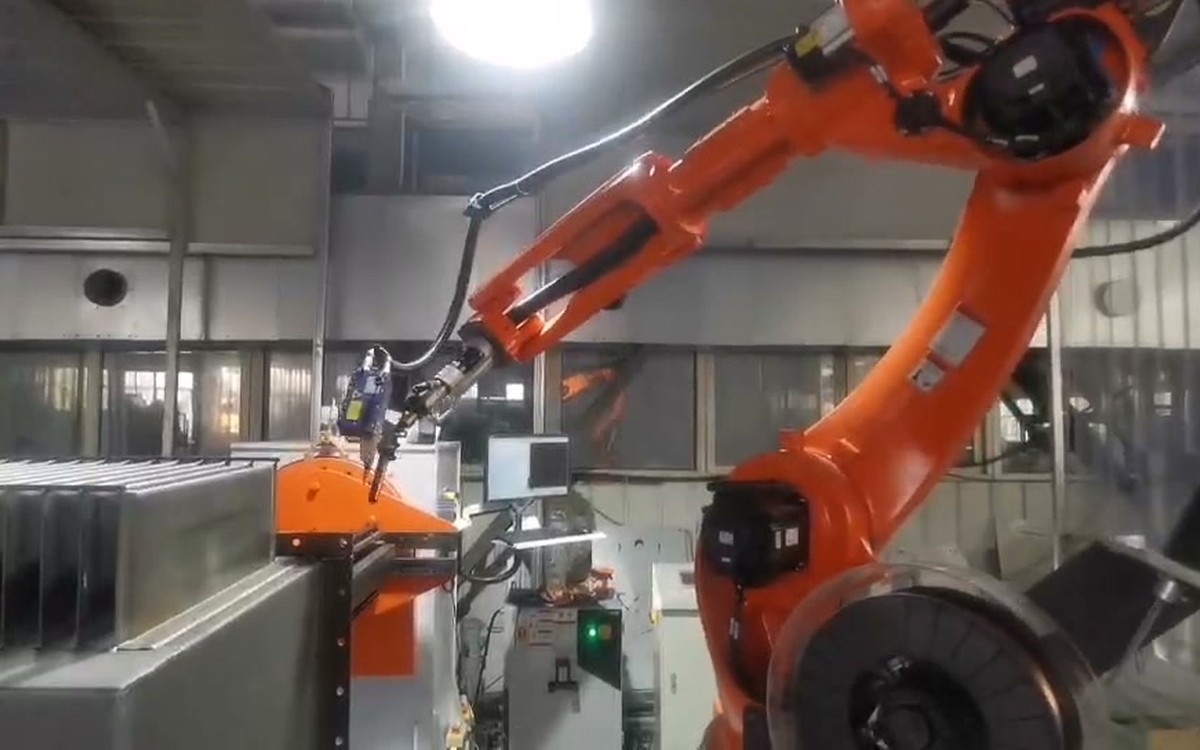
Rectangular tanks
Review side-wall seams, corners, corrugated sections and the orientation required for stable torch access.
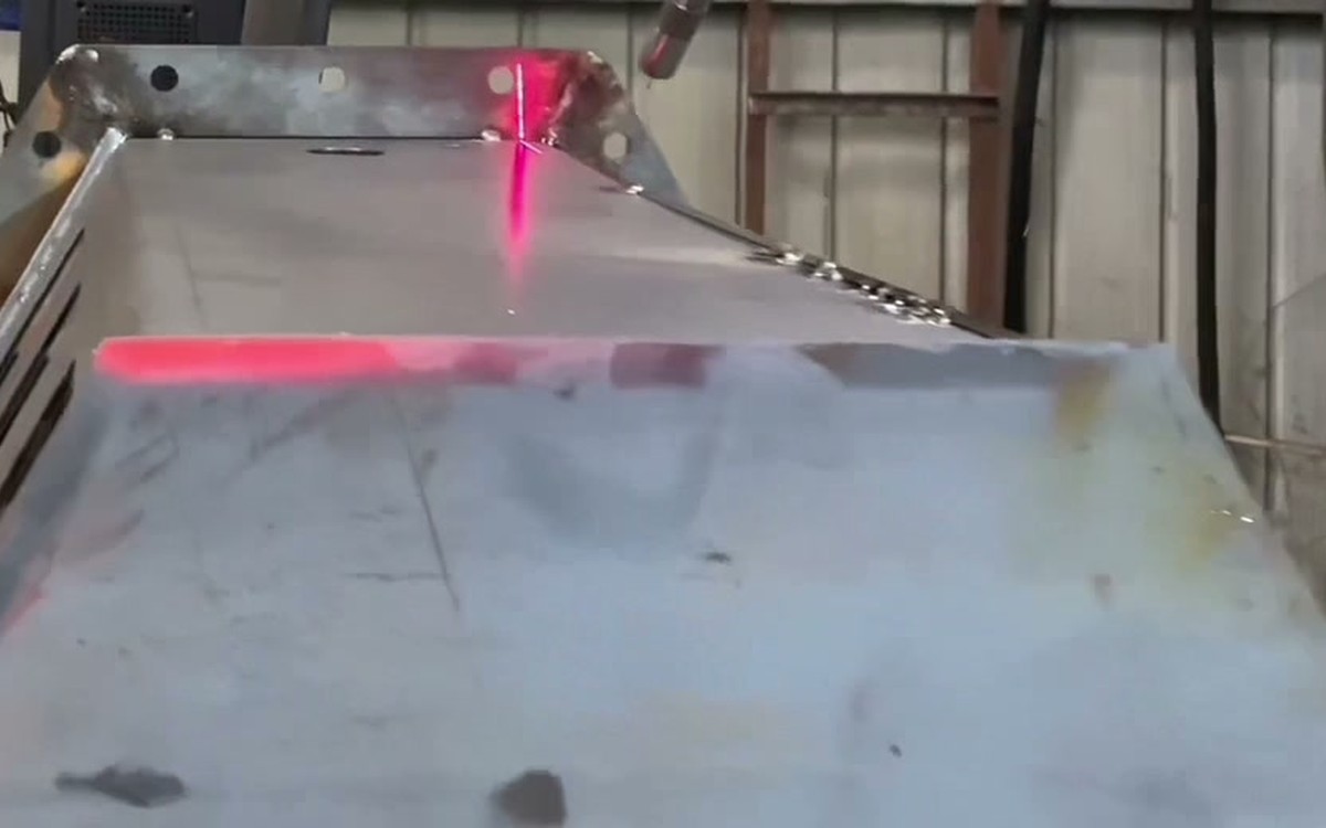
Triangular tanks
Plan path generation, laser localization and access around changing faces and internal geometry.
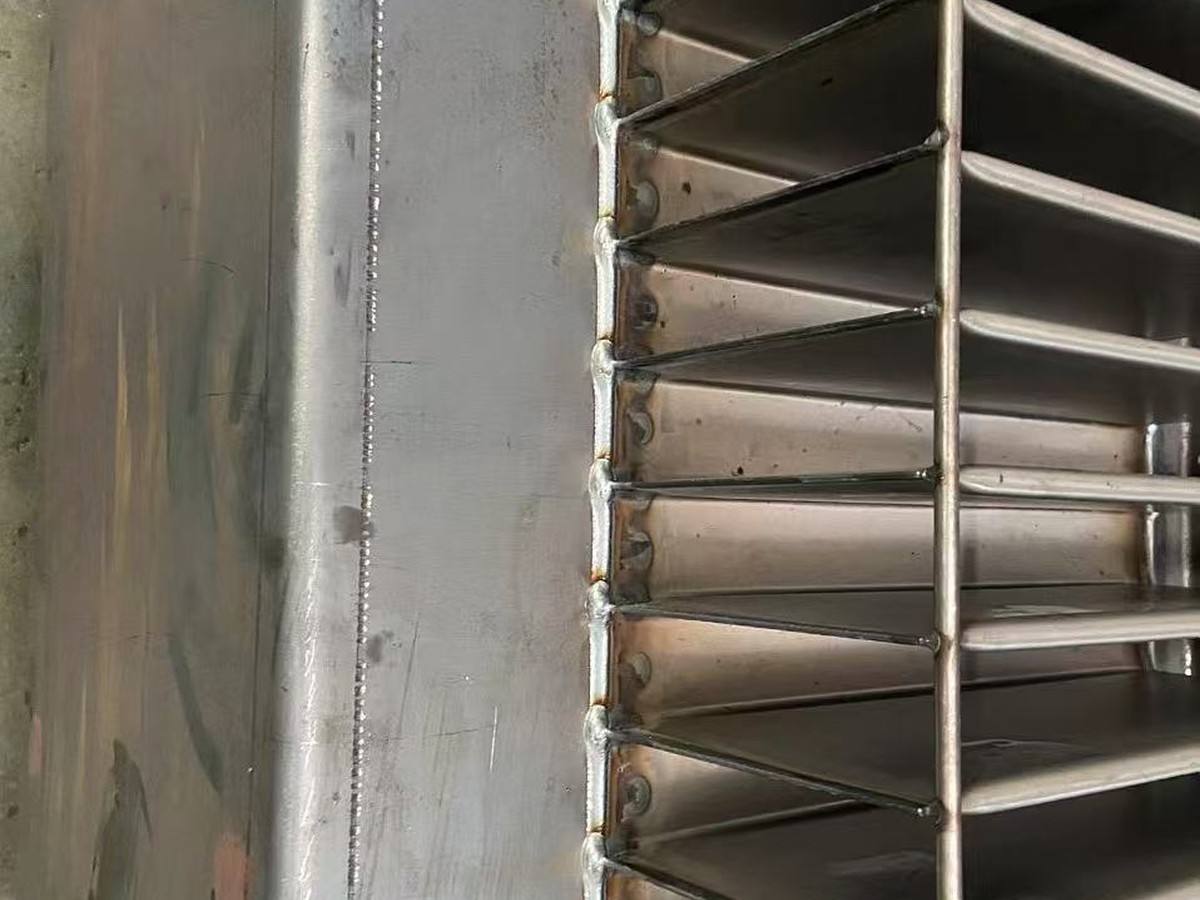
Corrugated-wall tanks
Separate continuous wall seams from fin-end joints and keep the weld path aligned across the repeated geometry.
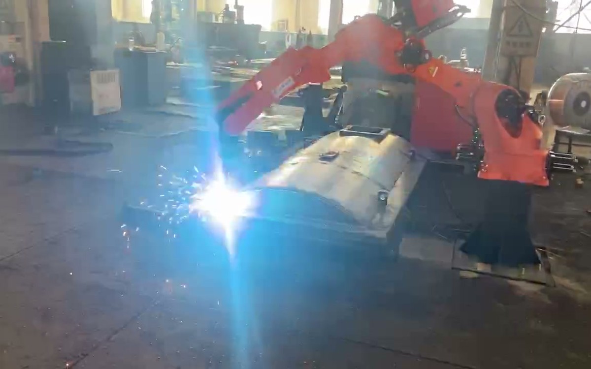
Tank covers
Review curved cover seams, openings, flanges and the fixture orientation needed for the selected cover design.
Turn the tank build into observable welding stages
The process is broken into workpiece stages so robot access, fixturing and acceptance can be checked at each stage instead of hidden inside one long production description.
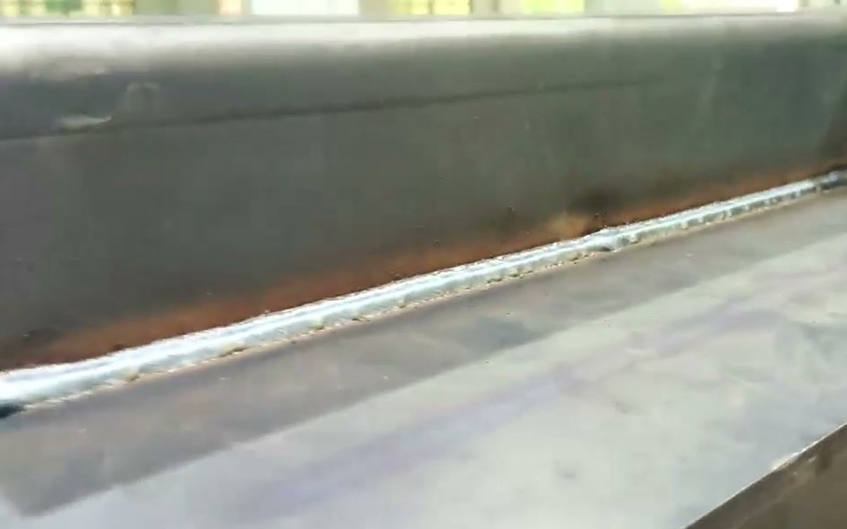
Tank bottom welding
Establish datums and complete the planned bottom seams before later tank geometry limits access.
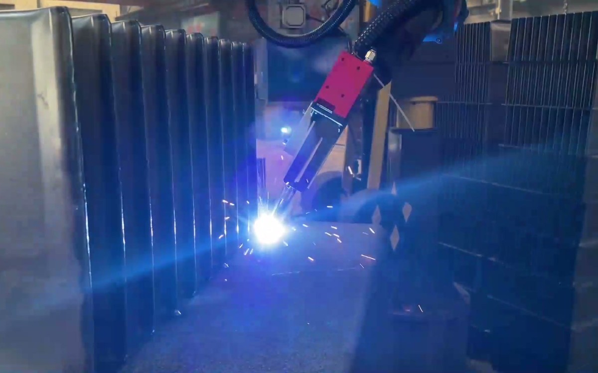
Walls and reinforcement ribs
Coordinate the wall, reinforcement and corrugated sections with fixture control and reachable weld orientation.
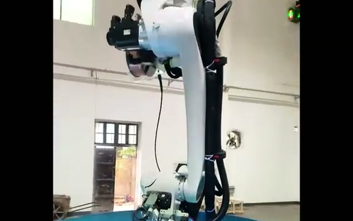
Internal welding
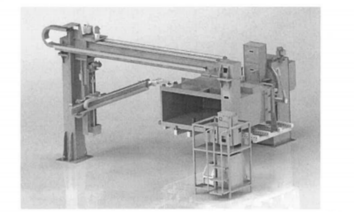
Use the selected inverted, column or travel-axis arrangement to reach the internal seams identified in the process plan.
External welding, transfer and internal welding
Keep the manual and automated stages visible from tack welding and palletizing through AGV transfer, crane unloading, repair welding and leak testing.
The entire fuel tank and the reinforcement ribs need to be manually spot welded and placed in the designated position on the special pallet.
The special pallet is placed on the designated pallet rack and waits for the AGV to transfer it to the external welding station robot for full welding.
After the external welding is completed, the AGV will transfer it to the internal welding station robot for full internal welding.
After the internal welding is completed, the AGV transports it to the unloading position, and the manual crane takes down the fuel tank and places it in the repair welding area, and then the manual repair welding leak test is performed. The AGV automatically returns to the loading area to wait.
Define each component by its job
The final bill of equipment is project-specific. These component roles show what must be coordinated before models, quantities and performance values are confirmed.
| Component | Responsibility in the application |
|---|---|
| Welding robot and process package | Maintain the programmed torch path and the selected gas-shielded arc-welding process around the defined joints. |
| Laser seam localization or tracking | Locate weld features and support path correction where the agreed fit-up condition requires sensing. |
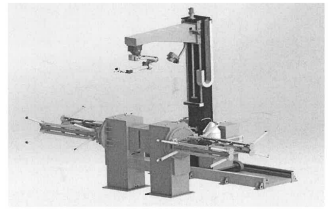
| Column, gantry or travel axis | Extend access across tank faces and into the internal welding envelope. |
| Positioner and dedicated fixture | Hold the tank from agreed datums and present seams in a workable orientation. |
| Pallet and AGV flow | Move the workpiece between loading, external welding, internal welding and unloading positions. |
| Controls and safety boundary | Coordinate motion, interlocks, recovery states and the final guarded operating scope. |
Leak testing belongs inside the production plan
Do not separate welding from leak-tightness verification
The existing workflow places manual repair welding and leak testing after unloading. The project should therefore define how weld appearance, seam continuity, dimensional requirements, repair disposition and leak testing are recorded.
Test method, pressure, duration and acceptance records are defined together with the customer specification and the approved project documents.
Need an external-to-internal welding review?
Send the tank drawing, joint sequence, loading method, acceptance plan and available floor space.
Make the automation boundary explicit
Application-first review
Start from the tank, joints, fit-up and acceptance method before selecting equipment.
Integrated architecture
Coordinate robot access, sensing, positioners, travel axes and material flow as one system.
Validation-led targets
Bind cycle, weld and changeover targets to real parts and an agreed test boundary.
Clear manual steps
Keep tack welding, crane handling, repair welding and leak testing visible in the scope.
Transformer tank welding questions
Which transformer tank types can this automation concept cover?
The solution can be reviewed for rectangular tanks, triangular tanks, corrugated-wall tanks and tank-cover work. Final coverage depends on the drawing, seam map, fixture concept and reachable welding orientation.
How are external and internal welding stations connected?
The workflow uses a dedicated pallet and AGV transfer. The AGV takes the tank to external welding, transfers it to internal welding, and then moves it to unloading before repair welding and leak testing.
Does a new tank type require complete reteaching?
Not necessarily. Offline programming, seam-node scanning and laser localization can reduce on-cell teaching work, but the result depends on model quality, fixture repeatability, calibration, sensing and the agreed changeover scope.
How is leak-tightness verified after welding?
The process includes a manual repair-welding and leak-test stage after unloading. The test method, pressure, duration, acceptance threshold and record format must be defined by the approved customer and project requirements.
What should I send for an application review?
Send the tank drawing, joint map, material and thickness, fit-up and tack-weld condition, expected variants, loading method, target output definition, inspection and leak-test plan, utilities and available floor space.
Start with the transformer tank drawing
EVST can use the workpiece, seam sequence, material flow and acceptance plan to review a practical external-and-internal welding architecture before project-specific parameters are fixed.