
Automobile Shock Absorber Intelligent Welding Production Line
Feel free to contact us on industrial robots and we will gladly answer any of your questions.
Two configurable production-line concepts connect component loading, pressing, welding, in-line checks, leak detection and physical reject isolation.
The scope shown here covers welded shock-absorber components. Final line design follows the actual workpiece family, joint map, inspection method and plant material flow.
Separate the welded component routes before designing the line
The source layouts describe two different part families. They are presented as separate line concepts so stations, handling and checks stay tied to the correct workpiece.
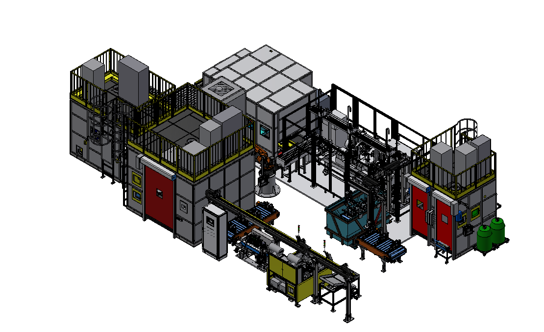
Front shock absorber component line
Pressing, double welding, forming and punching, oxide grinding, bracket-related welding, dimensional inspection and leak detection are connected in one routed concept.
(Typical welding objects)
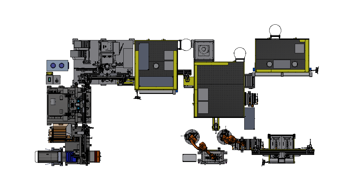
Secondary component line
The second route covers lifting-ring, yoke and lower-guard-plate related welding steps with orientation, appearance and part-position checks.
(Typical welding objects)
 Front shock absorber workpiece
 Lifting ring
 Yoke (fork arm)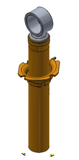
Put inspection and part disposition inside the production flow
The line concepts place checks before final offloading so accepted and rejected parts can follow different physical paths.
Process condition
Pressing, welding, cooling, punching and grinding establish the workpiece condition before downstream checks.
Part and position checks
The second route includes appearance, orientation, cylinder geometry and rolled-marking-position checks where applicable.
Dimensions and leak
In-line dimensional inspection and leak detection create explicit pass/fail decisions in the documented routes.
Physical disposition
Accepted parts leave the line; rejected parts are moved to a separate isolation path.
Automobile shock absorber (cylinder bottom, bracket, spring plate, bracket) intelligent welding production line
The protected component naming stays unchanged; the route identifies the two bracket operations by location.
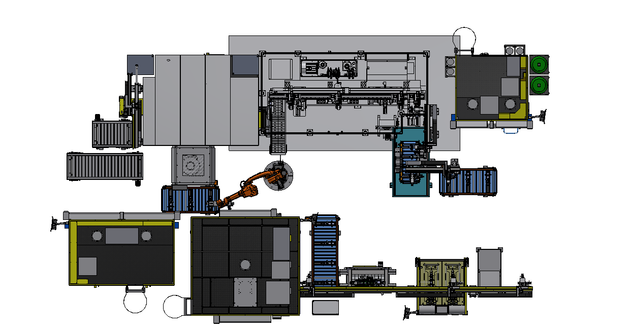
Production line process flow chart
Press-fit preparation leads through welding, forming, checks and disposition.
Inspection passed → normal offload
Inspection failed → isolation area
Customer case line configuration
Total personnel input for production line: 4-5 people according to the working conditions (1 person for cylinder bottom press installation, 1 person for spring plate welding station, 1 person for bracket projection welding (Some products do not have this process), 1 person for bracket welding, 1 person for leak detection/loading).
Applicable welding objects: front shock absorber of automobile.
Number of robots: 4 welding robots, 1 handling robot.
Automation rate: 94%
In-line conveying form: conveyor line, truss manipulator, slide, material rack and material frame.
Flexible switching form: quick change of fixture + program call.
This page presents a customer case. EVST adapts the solution and the design to each customer's actual project.
Automobile shock absorber (lifting ring, yoke, lower guard plate) intelligent welding production line
This route connects part presence and orientation checks with cylinder-bottom welding, lifting-ring or yoke operations, optional guard-plate welding, dimensions and leak detection.
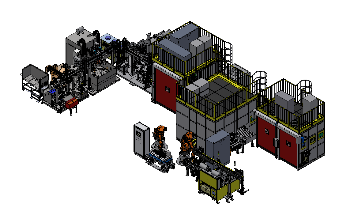
Production line process flow chart
The route uses conveyor, manipulator, slide and turntable handling according to the documented line configuration.
Checks passed → normal offload
Checks failed → isolation area
Customer case line configuration
Total production line personnel input: In addition to material delivery personnel, the production line personnel input 1-2 people (1 person for spring plate welding station (some products do not have this process), 1 person for leak detection/loading)
Applicable welding objects: automobile shock absorbers
Number of robots: 3 welding robots, 2 handling robots.
Automation rate: 99%
In-line conveying form: conveyor line, truss manipulator, slide, turntable, material rack and material frame.
Flexible switching form: quick change of fixtures + program call.
This page presents a customer case. EVST adapts the solution and the design to each customer's actual project.
Change fixtures and call the matching process program
Product variants still require confirmation of datum strategy, tooling interfaces, station compatibility and the inspection recipe before the changeover method is fixed.
Fixture interface
Define locating points, clamps, connectors and safe access for each workpiece variant.
Program call
Link the selected fixture and workpiece family to the corresponding station sequence and robot programs.
Verification after change
Confirm workpiece presence, orientation, joint access and required inspection points before returning the line to production.
Two line concepts, two material-flow architectures
The published indicators describe specific configurations, not universal performance guarantees.
Front component line
- Workpiece route
- Pressing, double welding, punching, grinding, bracket-related welding and inspection.
- Handling form
- Conveyor, truss manipulator, slide, rack and frame.
- Final checks
- Dimensions, leak detection and reject isolation.
Secondary component line
- Workpiece route
- Cylinder bottom, lifting ring, yoke and lower guard plate related stations.
- Handling form
- Conveyor, truss manipulator, slide, turntable, rack and frame.
- Final checks
- Part/position checks, dimensions, leak detection and reject isolation.
Build the concept from the real workpiece
EVST reviews the part drawing, joint map, material and fit-up condition, variant list, inspection method, loading route, floor space and utility conditions before fixing the line architecture.
Continue from welding into line planning and downstream validation
The three testing-machine resources below are separate downstream products; they are not included in the welding-line concepts shown on this page.
Scope boundary: this page addresses component pressing, welding, handling and the stated in-line checks. Oil filling, gas charging, damper assembly and damping-force testing are outside the shown welding-line scope unless defined as a separate project requirement.
Shock absorber welding line questions
Does this page describe a complete shock absorber assembly line?
No. It describes the component pressing, welding, handling and stated inspection routes shown in the source layouts. Other assembly and functional-test operations require separate definition.
Why are there two line concepts?
The layouts cover different welded workpiece families and different station sequences. Keeping them separate prevents equipment and process assumptions from crossing between parts.
How are rejected parts handled?
The documented routes create pass/fail decisions at dimensional and leak checks, followed by a separate isolation path for rejected workpieces.
What does flexible changeover require?
The published method combines quick fixture change with program call. The project still needs to confirm each variant, datum, fixture interface, station route and inspection recipe.
What does “rolled marking position” mean here?
It is the position of the rolled identification marking on the cylinder, checked as part of the documented orientation and geometry sequence where applicable.
What should I send for a line review?
Send part drawings, joint details, materials, fit-up conditions, variants, required production route, inspection and traceability requirements, floor space, utilities and the intended loading method.
Start with the workpiece, joints and acceptance route
Share the part drawings, workpiece variants, joint map, production route, required checks, traceability needs and layout constraints. EVST can then define the stations and material flow around your actual process.