
Robotic Axle Welding Workstation
EVST configures the robot, welding package, positioner and fixture around the actual axle component, joint geometry and production route.
Start with one workstation, add the guarded cell functions your plant requires, or connect several stations into a production line after loading, inspection and material flow are defined.
What an axle welding workstation defines
Build the cell around the axle and its joints
Axle welding automation works best when the component definition leads the design. EVST maps the welds, handling points, fixture datums and inspection route before fixing the equipment layout.
Define what the station must weld
Name the axle component, identify every production joint and record where the torch must approach. Housing geometry, brackets, seams and access restrictions shape the robot posture and the need for workpiece rotation.
- Drawing revision and component orientation
- Joint sequence, process and acceptance criteria
- Fit-up variation and tack-welding condition
Present a repeatable workpiece
The fixture establishes the locating datums and keeps the assembly stable through loading and welding. The positioner presents each seam at a useful angle while maintaining access for the torch, cables and service tasks.
- Loading direction and operator reach
- Clamping sequence and changeover method
- Rotation, clearance and cable routing
Coordinate motion with the welding package
The robot path, workpiece motion and welding parameters must work as one process. EVST plans starts, stops, transitions, torch access, cleaning and recovery around the joint sequence instead of treating the robot as an isolated device.
- Robot and positioner coordination
- Torch service and consumable access
- Sensing strategy where the joint requires it
Agree how results will be checked
A useful acceptance plan separates equipment function from part quality and production output. EVST aligns the run-off method with the customer’s weld inspection, dimensional checks, loading method and agreed cycle boundary.
- Weld and dimensional inspection route
- Production trial and recovery scenarios
- Safety and operator interaction checks
Choose a workstation, cell or production line
The right scale depends on how many operations must be connected, how parts enter and leave, and where inspection or manual work belongs.
| Format | Best fit | Typical integration focus | Planning question |
|---|---|---|---|
| Axle welding workstation | One defined welding operation with local loading and unloading. | Robot, welding package, positioner, fixture and station controls. | Can one unit complete the required joint set and remain easy to load? |
| Robotic welding cell | A protected automation area with coordinated production functions. | Guarding, interlocks, operator access, process services and recovery. | Which interactions, service points and safety functions belong inside the cell? |
| Axle welding production line | Several connected operations with planned transfer and line control. | Material flow, buffers, station balance, inspection routing and supervision. | Which operation controls line output, and how should parts move between stations? |
Four elements that shape the welding station
EVST brings the motion, process and workholding elements together around the required weld path.
Welding robot
Provides the motion envelope and torch orientation for the defined joints. Selection follows the required poses, access and tooling load.
Welding package
Combines the power source, torch, wire delivery and process interfaces needed for the chosen welding method.
Workpiece positioner
Supports and rotates the axle assembly so the robot can reach seams in a productive welding orientation.
Dedicated fixture
Locates the actual components, establishes datums and supports a controlled clamping and loading sequence.
From drawings to an accepted production process
Each step converts application inputs into a testable station decision.
What to send for a useful axle cell review
A compact application pack lets EVST focus the first concept on the real workpiece instead of assumptions.
Workpiece definition
Share the assembly drawing, component list, joint map, material, thickness and the expected fit-up condition. Mark critical datums and surfaces that must remain accessible.
Production route
Describe loading, unloading, tack welding, cleaning, changeover, inspection and repair. Include the intended shift pattern and the boundary used for the production target.
Quality plan
State the weld acceptance method, dimensional checks, sampling approach and cosmetic expectations. These requirements guide the process trial and station run-off.
Plant integration
Provide the available floor space, utilities, upstream and downstream interfaces, operator access and maintenance route. Note any planned transfer or line-level controls.
Robotic welding for tubular bicycle, electric-vehicle and motorcycle frames
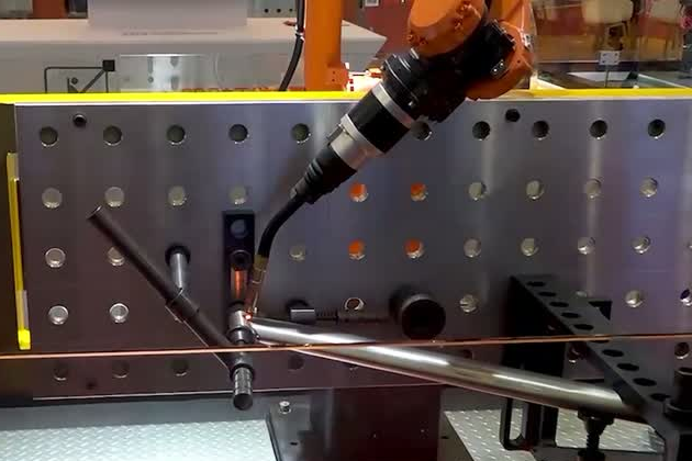
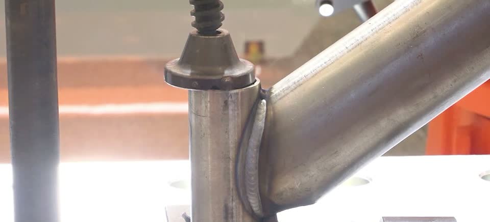
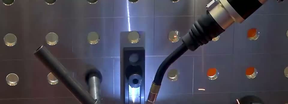
EVST applies coordinated robot and positioner motion to the compact, changing paths found around tubular frame joints. The process focus is stable torch access, controlled motion through transitions and a finish that matches the agreed acceptance standard.
Confirm performance on the actual workpiece
The final concept and acceptance plan connect robot behavior to the customer’s part, process and production route.
Production timing
Use one agreed clock. Include the applicable loading, welding, cleaning, changeover, inspection and recovery steps so the result represents the planned station.
Welds and dimensions
Check the complete process. Fit-up, fixture behavior, tool center point, heat input, sensing and inspection all contribute to the finished part.
Automation responsibility
Assign every operation. Define which loading, tack welding, inspection, repair, grinding and maintenance tasks belong to automation and which remain with operators.
Axle welding workstation questions
What is the difference between a workstation, cell and production line?
A workstation is one focused production unit. A welding cell adds the protected automation area, controls and planned operator interactions. A production line connects several loading, welding, inspection or transfer stations through material flow and line-level coordination.
What information does EVST need to configure an axle welding cell?
Send the part drawing, component and joint map, material, thickness, fit-up condition, welding process, loading method, production target, inspection method, plant layout and utilities. These inputs allow the concept to reflect the real axle and production route.
How does a positioner support axle welding?
The positioner supports and rotates the workpiece so the robot can maintain torch access and a useful welding orientation. EVST selects the positioner format and motion around the axle assembly, fixture, required poses and handling sequence.
How does EVST confirm cycle time and weld quality?
The project first defines the cycle boundary and acceptance method. EVST then validates the motion, welding process, loading sequence and inspection route with representative parts so the result can be compared with the agreed requirement.
Can robotic welding reduce secondary grinding on tubular frames?
It can reduce manual finishing when the tuned welding process, joint condition, spatter level and bead appearance meet the customer’s acceptance criteria. The confirmation belongs in the process trial for the actual frame material and cosmetic standard.
Start with the axle drawing and acceptance method
Send the component drawing, joint map, material, fit-up condition, loading route, production target, inspection plan and available floor space. EVST will use those inputs to shape the workstation, guarded cell or connected line concept.