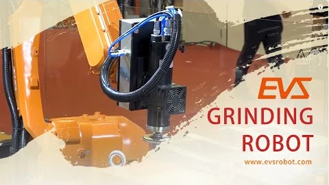
Robotic Grinding and Polishing Workstation — Models, Force Control and Dust Extraction
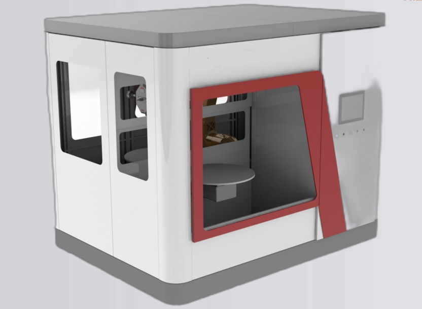
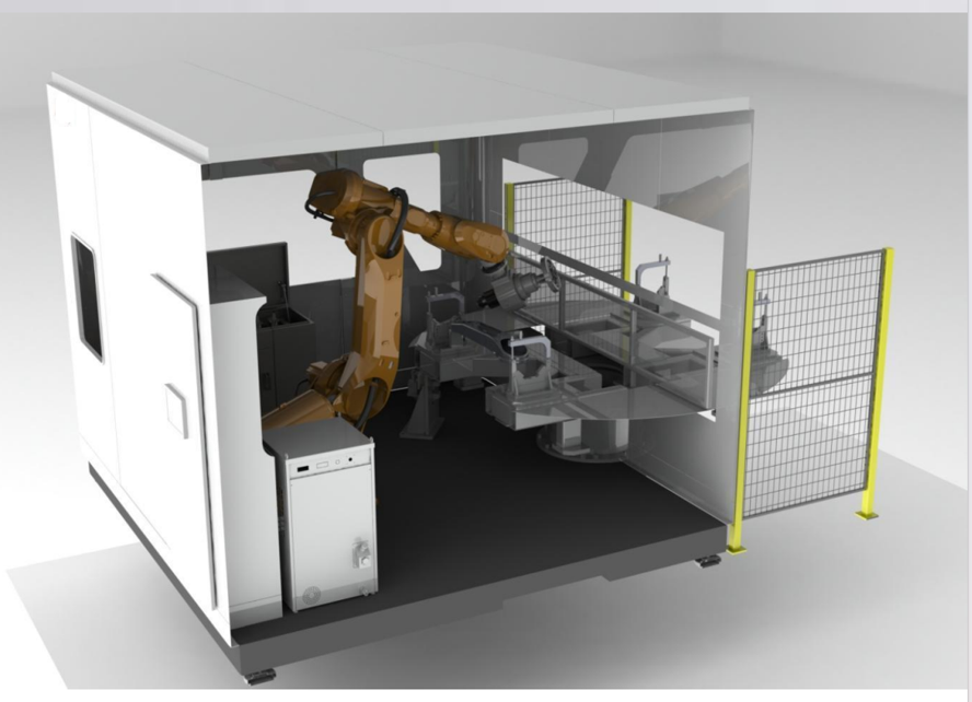
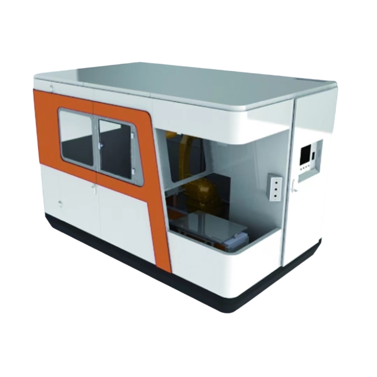
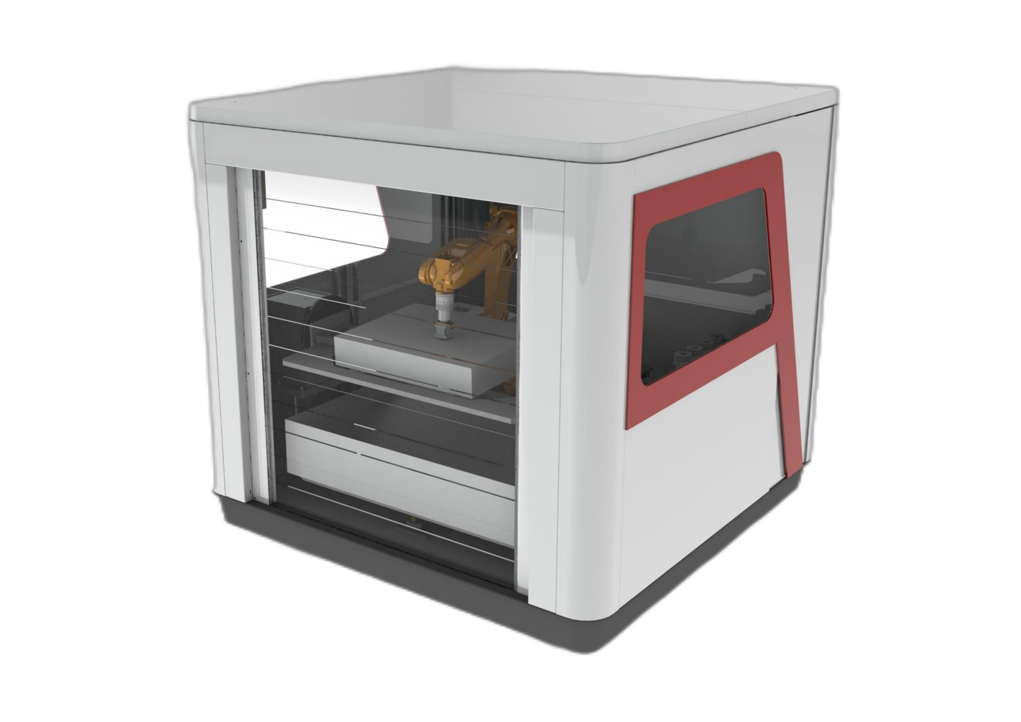
A robotic grinding and polishing workstation uses an enclosed body to contain dust and a modular layout for maintenance, modification and upgrades, combining robot-guided finishing with suitable force-control and dust-extraction equipment.
- The enclosed body helps contain dust around the finishing process.
- A modular layout allows access for maintenance, modifications and later upgrades.
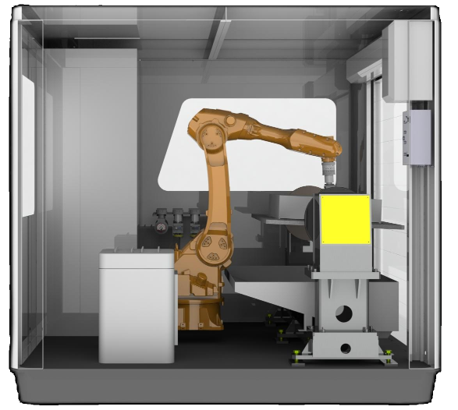
- The robot carries the workpiece for finishing, with deburring also supported.
- Monitoring functions cover broken tools and belts, tool life and production capacity.
- Belt grinders use pneumatic floating as standard, with electronically controlled constant-force floating available as an upgrade.
- The double-layer material table incorporates a dust-resistant design.
Part-held or tool-held: start with the workpiece
Robot carries the part
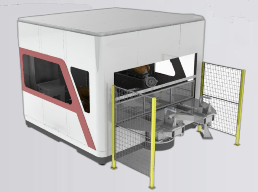
For parts up to 30 kg, a part-held arrangement can take the workpiece directly from the loading position to a fixed finishing station. It can reduce per-part handling steps, while the surrounding stations require more floor space.
Robot carries the tool
In a tool-held arrangement, the robot brings the tool to a larger or heavier workpiece. The layout can be more compact, while tool and abrasive changes add steps to the single-part cycle.
The 30 kg figure is a route-selection boundary, not the permitted part weight for every model. The model table below separately defines robot payload and recommended part weight.
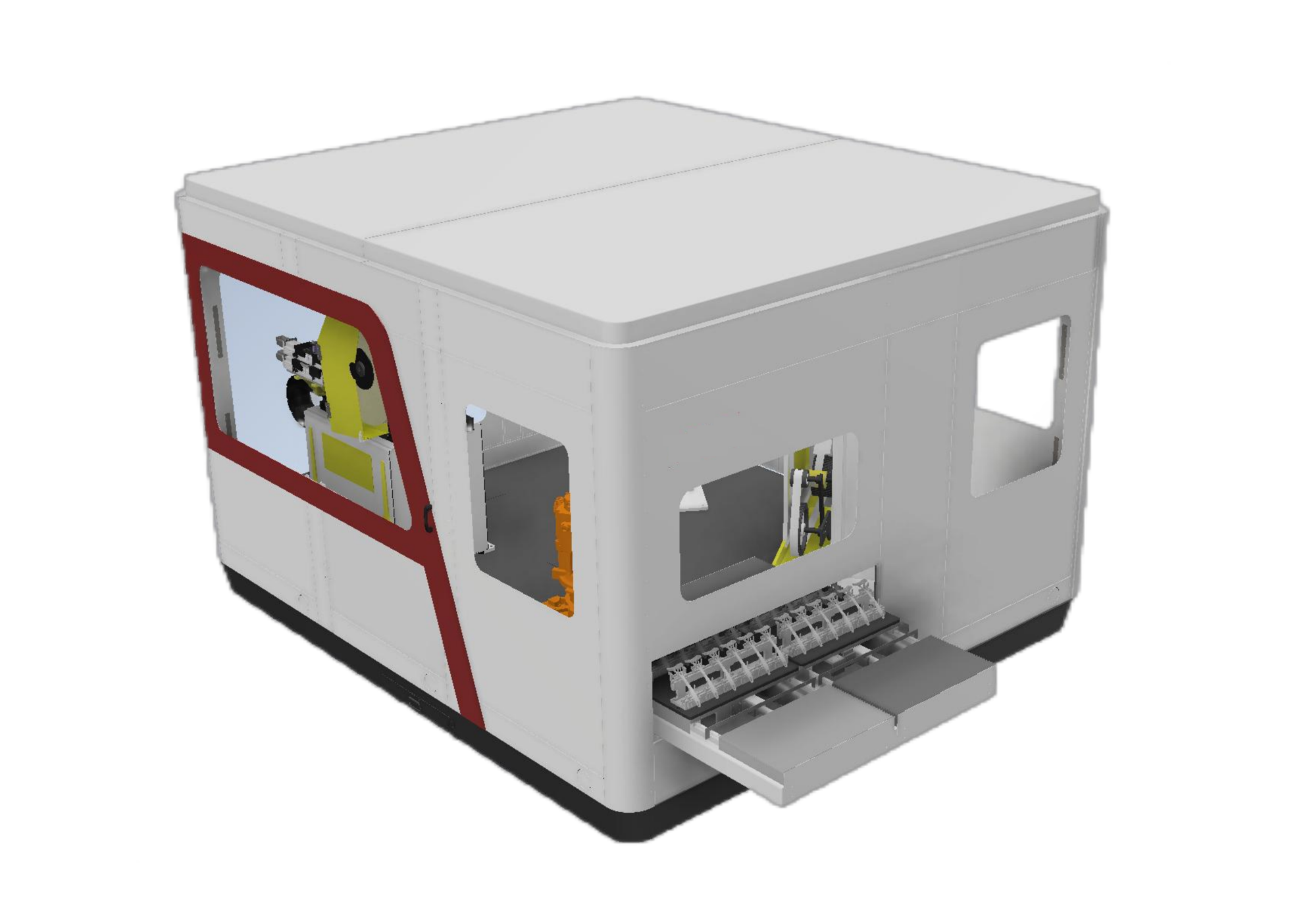
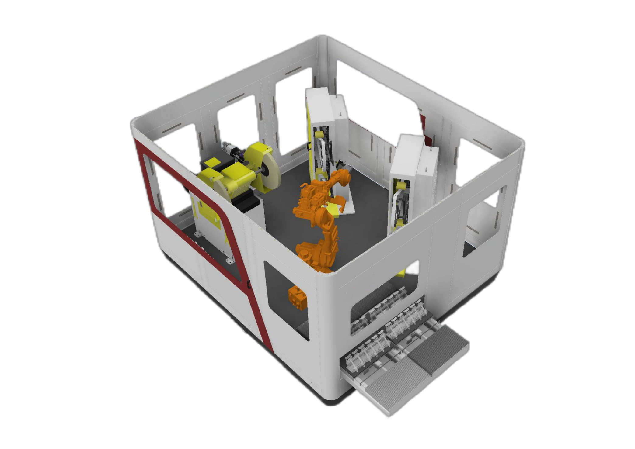
Workstation model specifications
Compare the supported model ranges for a part-held configuration. Part dimensions, part weight and robot payload are separate limits; select a row that accommodates the workpiece.
Scroll horizontally to compare every field.
| Model | Robot payload | Part weight | Part envelope | Overall dimensions | Supply / rated power | Grinding accuracy |
|---|---|---|---|---|---|---|
| EVSPG-10A | 10 kg | ≤3 kg | 100 × 100 × 50 mm | 3450 × 2200 × 2260 mm | AC 380 V / 11.5 kW | ±0.1–0.2 mm |
| EVSPG-20A | 20 kg | ≤7 kg | 200 × 200 × 100 mm | 3450 × 2200 × 2260 mm | AC 380 V / 12.5 kW | ±0.1–0.2 mm |
| EVSPG-30A | 30 kg | ≤15 kg | 300 × 300 × 150 mm | 3450 × 2200 × 2260 mm | AC 380 V / 13.5 kW | ±0.1–0.2 mm |
| Applicable materials | Aluminum castings, small hardware | |||||
| Industrial robot | EVST | |||||
The accuracy field describes grinding accuracy. Robot motion requirements are compared separately below.
Standard grinding and polishing modules
Standard modules include dual-station belt grinders, single-station belt grinders and single-station polishing machines. Wide-belt, large-part and small-part polishing modules support modular combinations, with floating and automatic-compensation arrangements.
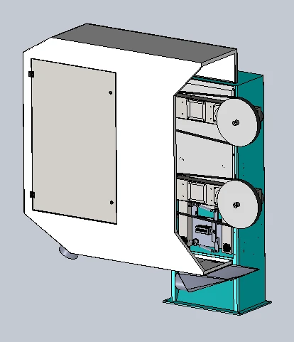
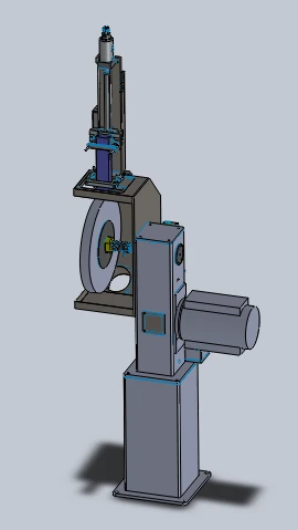
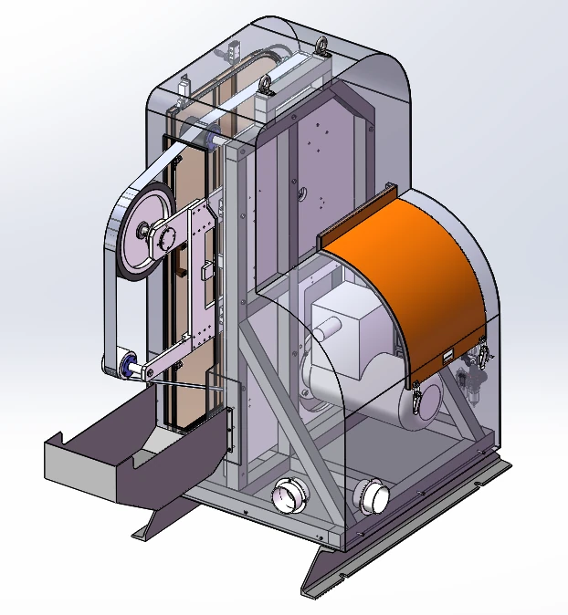
One belt-machine configuration uses a 4 kW explosion-proof drive motor, a maximum rotational speed of 2800 rpm and a 2800 mm × 70 mm abrasive belt. It includes belt tracking, a dust-hopper connection, standard pneumatic floating with an electronic constant-force upgrade option, and provision for a floating spindle.
Seven consumable families and their roles
Consumable selection follows the required operation and contact shape. Different stations can be combined to move between abrasive removal and polishing steps.
Abrasive belts
Belt grinding along the selected contact path.
Flap wheels
Abrasive finishing with a wheel-form consumable.
Nylon wheels
Surface polishing with a nylon-wheel station.
Sisal wheels
Wheel polishing within the required finishing sequence.
Cloth buffing wheels
Buffing with a cloth-wheel station.
Files
Localized filing and edge deburring.
Milling cutters
Milling and material removal before subsequent finishing.
Force controlled robotic grinding
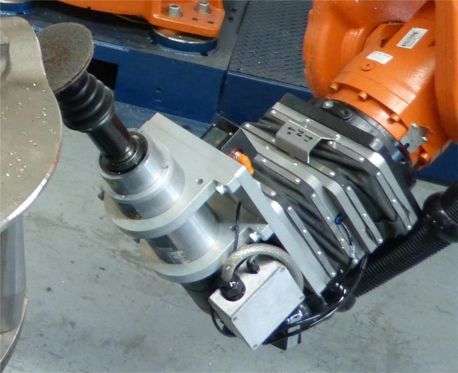
Passive pneumatic compliance
A proportional valve controls pressure inside the floating mechanism, with the control setting adjusted for robot posture. Mechanical compliance provides a floating range of ±10 mm.
Active force feedback
Force feedback adjusts the floating device forward or backward to maintain contact as the part position, part tolerance or abrasive wear changes. The controlled force range is on request.
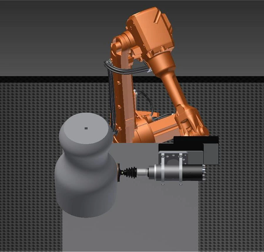
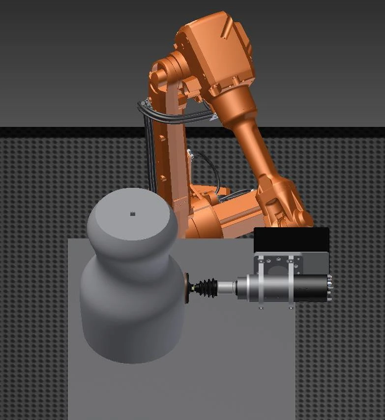
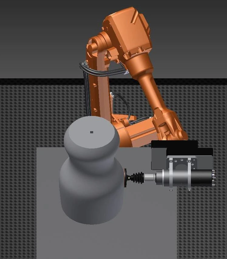
An all-position force/position-control tool option supports automatic tool changes and is specified for continuous duty with IP65 protection. These are tool-option specifications, separate from the robot-body requirements.
Tool and force-control equipment options
Tool families
- Oscillating floating spindle
- Oscillating spindle
- Floating rotary file
- Force-controlled floating heavy grinder
- Force-controlled belt grinder
- Fixed belt grinder
Force-control equipment forms
- All-position force-control equipment
- Unidirectional force-controlled grinder
- Bidirectional dual-station force-controlled grinder
- Force-controlled deburring equipment
Radially floating electric spindles are another tool-interface option. Select the tool family around the operation, contact direction and available access.
Dust extraction and the working enclosure
The cartridge-filter configuration uses negative-pressure filtration, PTFE-coated filter media and pulse cleaning with drawer collection. Its technical values are shown below.
| Technology item | Parameter value | Unit |
|---|---|---|
| Power | 7.5 | kW |
| Airflow | 8500 | m³/h |
| Filter cartridges | 6 | cartridges |
| Filter area | 66 | m² |
| Filtration size | 0.3–1 | μm |
| Filtration efficiency | 99 | % |
| Compressed air pressure | 0.4–0.6 | MPa |
| Collection bins | 40 × 2 | L |
| Noise level | 78±2 | dB |
| Inlet connections | 4 × 200 | mm |
| Overall dimensions | 1350 × 1100 × 2280 | mm |
| Supply voltage | 380 | V |
| Supply frequency | 50 | Hz |
Enclosure and dust interfaces
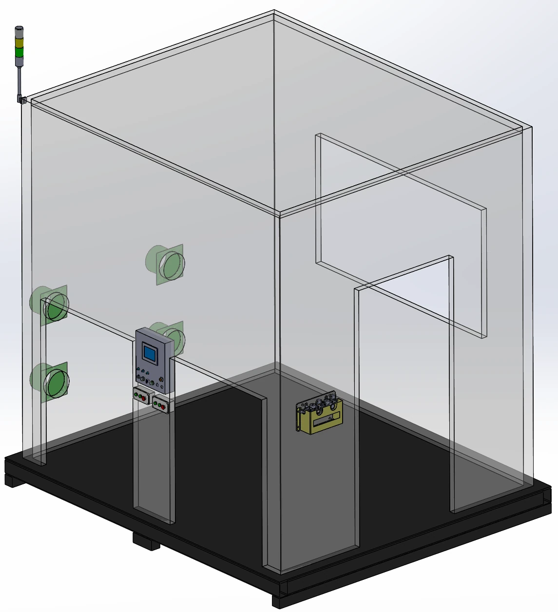
An aluminium-profile enclosure with sheet-metal panels includes a 5 mm acrylic viewing window, lighting and 4 extraction connections. A display panel, loading-confirmation button box, maintenance door and Q235 carbon-steel base with forklift access complete the arrangement.
Wet extraction and integrated dust control
Wet extraction is an available route for aluminium and magnesium dust. The workstation body can contain dust with an outer shell, dust-resistant double-layer table design and dust-hopper connections; dust detection and alarms are configuration options.
Robot motion and protection requirements
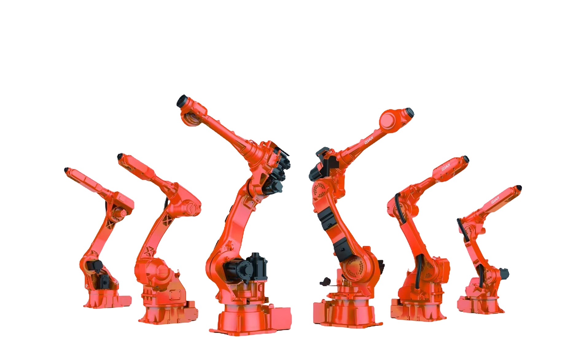
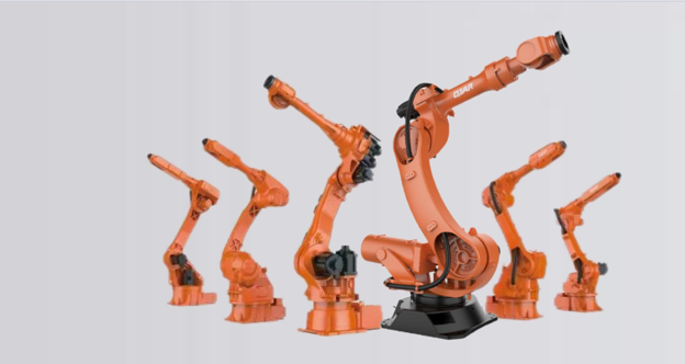
Select a six-axis robot for the application, using these motion and protection requirements as a comparison checklist. These are robot-selection conditions, separate from workstation grinding accuracy and the controlled contact-force range.
- Robot repeatability
- ±0.02 mm
- Effective linear speed
- ≥5 m/s
- TCP accuracy
- 0.2 mm
- Path accuracy
- ≤0.2 mm At grinding speeds up to 300 mm/s
- Robot protection
- IP67
- Contact-load reference
- 3–10 kg
Inline condition monitoring
Consumable and tool condition
Available functions include broken-belt detection, broken-tool detection and tool-life management. Tool lubrication can be included for the selected grinding-tool configuration.
Production status
Production-capacity management complements consumable monitoring. Review the required signals and maintenance access alongside the selected tool and enclosure layout.
FSW seam finishing
Aluminium battery-tray FSW seams
A typical application is robot-guided grinding of friction-stir-welded seams on aluminium battery trays.
Double-sided FSW finishing
A separate double-sided application combines a force-controlled spindle, a turning positioner and wet extraction to grind 6 FSW seams: 3 on the front and 3 on the reverse.
Related frame-finishing operations
Related battery-frame operations include weld-face milling, deburring and grinding sealing faces after milling.
Automated grinding line: workstation interfaces
When planning an automated grinding line, start with the workstation interface: incoming part location, transfer access, extraction connections and the signals shared with surrounding equipment. Match the layout to the finishing sequence and the required access for tool changes and maintenance.
Part-held or tool-held — how do I choose for my part?
Use the part-held route as a selection starting point for parts up to 30 kg, then check the model-specific part weight, gripping access and finishing path. Larger or heavier parts suit a tool-held arrangement. The model table gives narrower part limits than this general route criterion.
What robot payload and part weight does each workstation model cover?
The three model rows pair robot payloads of 10, 20 and 30 kg with recommended part weights up to 3, 7 and 15 kg respectively. Robot payload and part weight are different selection fields; use both together with the part envelope.
Passive floating or active force control — which one does my part need?
Passive pneumatic compliance provides mechanical floating travel. Active force feedback adjusts displacement to compensate for part-position changes, part tolerances and consumable wear while maintaining contact. Select the approach around the surface and its variation.
What contact force range can be held?
The controlled contact-force range is on request. Discuss the workpiece material, geometry, finishing tool and target surface before selecting the force-control configuration.
What dust extraction is required for aluminium and magnesium dust?
Wet extraction is an available route for aluminium and magnesium dust. Discuss the material and process when choosing extraction and enclosure equipment; the cartridge-filter specifications describe a separate configuration.