
A machine tending handoff is ready to evaluate when the receiving fixture can support and locate the part before the gripper releases it, and the released gripper has a clear route out. Check those two conditions separately: a disc can enter a machine opening while the fingers, wrist or attached lines still lack room to withdraw.
Follow the support through the machine opening
The video follows an articulated arm working between a rack of round parts and a machine. At 00:04, a disc and the gripping arrangement are visible near the rack. The views at 00:12 and 00:17 place the arm at the machine opening; by 00:28 its posture has changed again. These selected views help locate the handoff problem. They do not expose the machine’s complete internal seating arrangement or its control signals.
For an application drawing, mark three things: the contacts that carry the part before pickup, the contacts used during transport, and the receiver contacts required after release. A gripper can provide transport restraint without defining the machining datum. Conversely, a part touching a receiver has not necessarily reached its intended seat.
Carr Lane’s locating and clamping guidance distinguishes placing a workpiece relative to the tooling from holding it in that position. That distinction is useful here: the transfer review needs a defined receiving condition, not just a robot destination point. The reference explains a workholding principle; it does not identify the mechanism inside the filmed machine.
Draw the tool after release
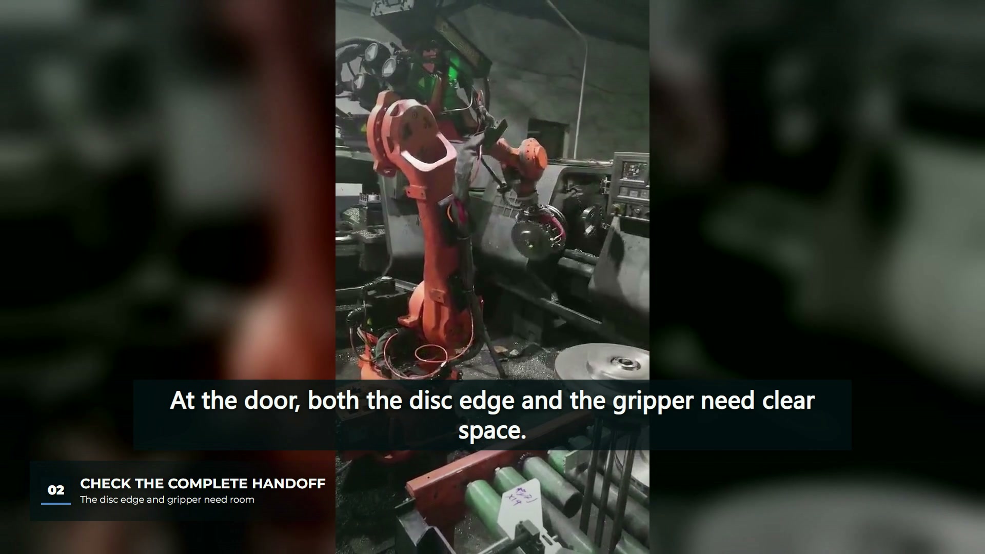
Overlay the held-part shape and the released-tool shape on the same section through the opening. Include the fingers in their actual release position, any second gripping position, the wrist adapter and the services that move with the wrist. Do not assume that opening the gripper makes the assembly smaller in every direction.
This exposes two different layout failures. In one, the disc clears the doorway but an opened finger cannot pass the receiver. In another, the tool can retract locally, yet its turn toward the rack brings the wrist or services close to the door frame. They need different remedies: receiver or finger geometry for the first, an altered exit direction or connecting route for the second. Neither is resolved by checking the disc diameter alone.
The comparison should use the actual gripper configurations and machine geometry. A photograph supplies useful locations to inspect, but perspective and hidden surfaces make it unsuitable for assigning a clearance value. Leave that dimension undecided until it can be taken from the model, drawing or a controlled physical check.
Specify the handoff condition before the timing
Use a short sequence description to connect mechanical duties to the machine interface:
| Transition | Condition to define for the proposed cell |
|---|---|
| Rack to gripper | How correct engagement is established before the part leaves its support |
| Gripper to receiver | What confirms the required seat and restraint before release |
| Release to withdrawal | Which tool configuration is active and what establishes a usable exit |
| Withdrawal to machine operation | How the machine receives confirmation that the robot and tooling are clear |
These are design questions, not a description of control logic proven by the video. The signal names, fault responses and permitted operating states must come from the actual machine and integration requirements. Our related discussion of lathe tending handoffs and interlocks addresses that interface in more detail.
The useful outcome of this review is a support-and-exit drawing with unresolved contacts and clearances marked. Clamping force, seating repeatability and machining accuracy remain separate acceptance questions. A smooth transfer may justify investigating the layout; it cannot supply those results. For a disc-handling proposal, the most informative next evidence is the receiver section together with the gripper in its held and released states.