
Robotic Welding Cell Configurations for Light and Medium Workpieces
A robotic welding cell organizes the robot, process equipment, workholding, controls and safeguards around a defined part family. This page compares six enclosed arrangements by workpiece motion, envelope and robot count. Component-level integration and layout engineering are covered in the linked technical guides.
Shortlist by workpiece motion first
Six arrangements cover flipping, horizontal rotation, multi-axis positioning and end-supported rotation. Start with the selection logic here, then use the detailed cards and table to compare available values.
Dual-station wide flip cell
One robot serves two flip positioners for longer rectangular fixtures inside a fully enclosed welding room.
Compact dual-station flip cell
A smaller fixture envelope keeps the same two-positioner flip principle for compact parts.
Twin-station horizontal rotary cell
Horizontal rotation presents circular or indexed weld faces to one or two robots.
Vertical three-axis positioning cell
Three controlled axes reorient an elongated fixture while retaining the interfaces required for the fully enclosed welding room.
Horizontal three-axis positioning cell
Horizontal rotation combines with additional positioning axes for wider fixture coverage.
Dual-robot headstock-tailstock cell
Two robots work around two end-supported positioners with automatic in/out movement and length adjustment.
Review each arrangement against the real part family
Dimensions are the applicable fixture or workpiece envelopes for each configuration. Final tooling, weld access and clearances remain project-specific.
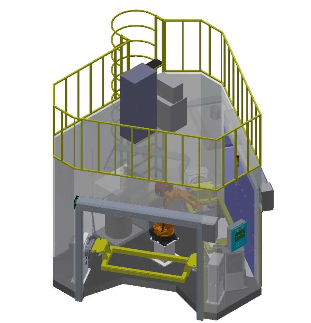
Dual-station wide flip cell
One robot serves two flip positioners for longer rectangular fixtures inside a fully enclosed welding room.
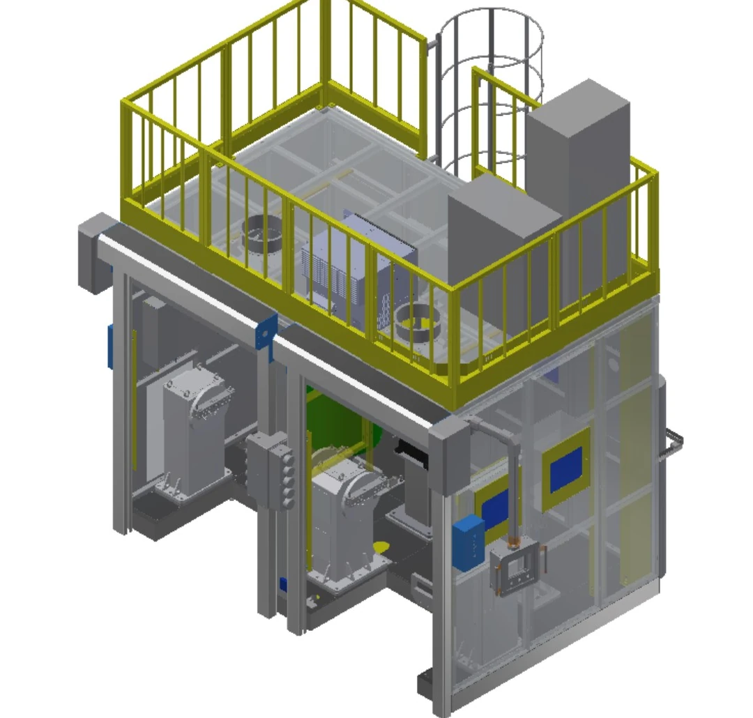
Compact dual-station flip cell
A smaller fixture envelope keeps the same two-positioner flip principle for compact parts.
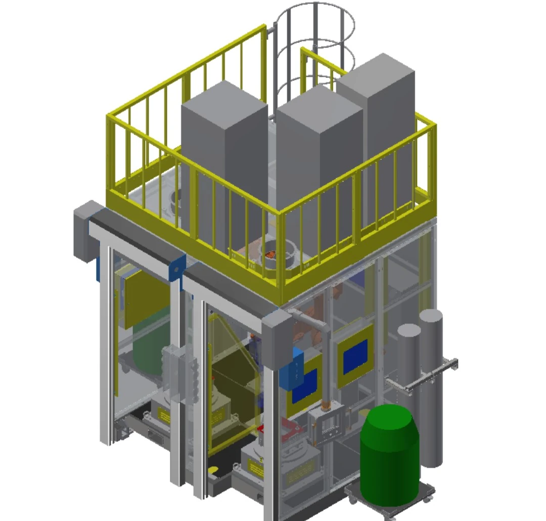
Twin-station horizontal rotary cell
Horizontal rotation presents circular or indexed weld faces to one or two robots.
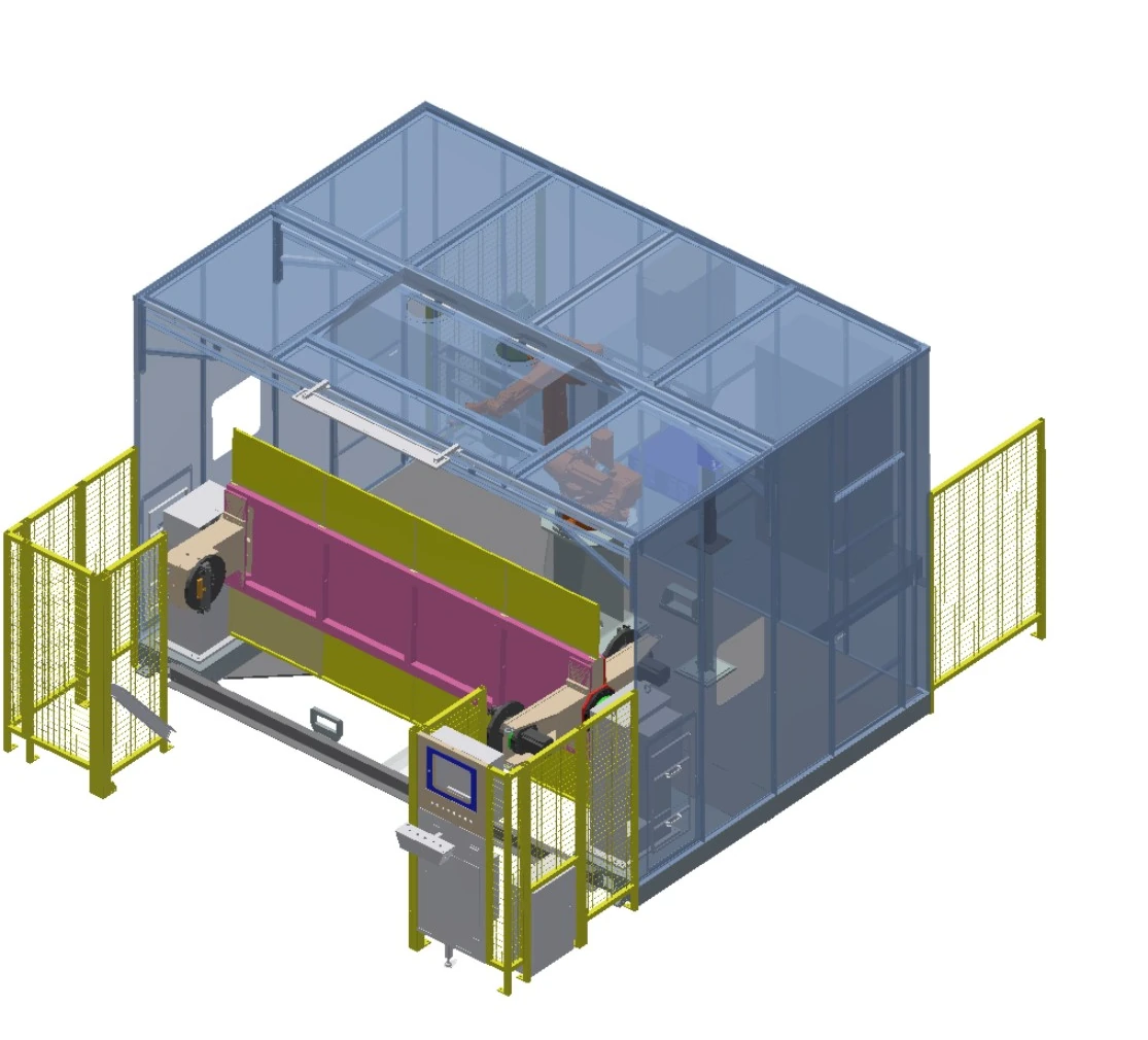
Vertical three-axis positioning cell
Three controlled axes reorient an elongated fixture while retaining the interfaces required for the fully enclosed welding room.
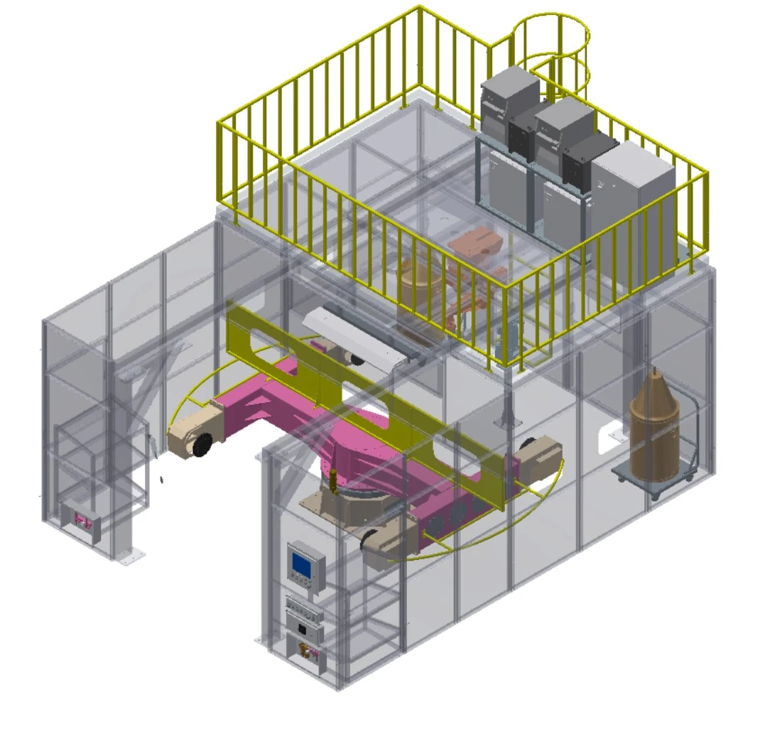
Horizontal three-axis positioning cell
Horizontal rotation combines with additional positioning axes for wider fixture coverage.
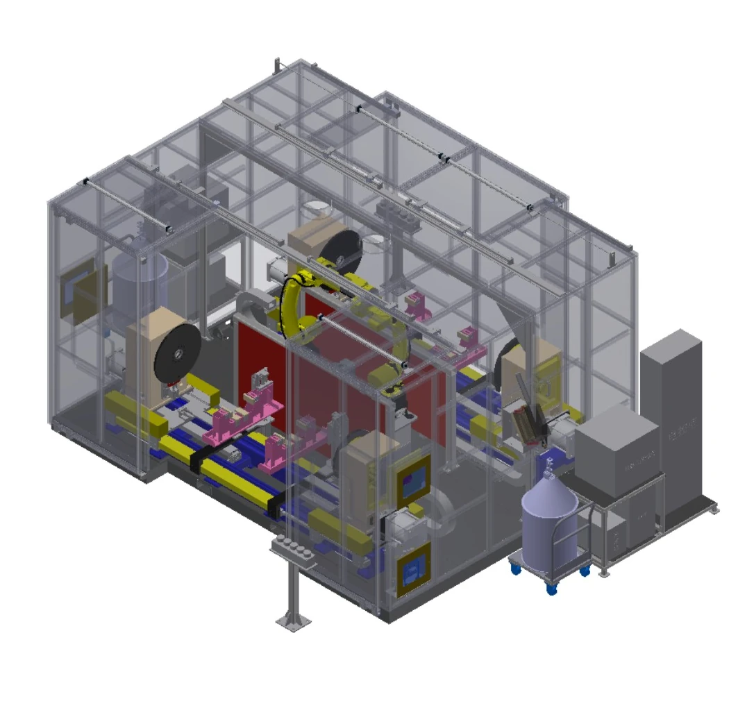
Dual-robot headstock-tailstock cell
Two robots work around two end-supported positioners with automatic in/out movement and length adjustment.
Compare six arrangements on one set of fields
| Row | Descriptive configuration | Robots | Arm reach | Positioning arrangement | Load | Applicable envelope | Stations |
|---|---|---|---|---|---|---|---|
| A | Dual-station wide flip cell | 1 | 1.4 m / 2 m optional | Single-axis flip | 500 kg | Fixture 1.8 m × 0.8 m | 2 positioners |
| B | Compact dual-station flip cell | 1 | 1.4 m | Single-axis flip | 500 kg | Fixture 0.8 m × 0.5 m | 2 positioners |
| C | Twin-station horizontal rotary cell | 1 or 2 | 1.4 m | Single-axis horizontal rotary table | 500 kg | Rotation ≤1 m; height ≤0.5 m | 2 positioners |
| D | Vertical three-axis positioning cell | 1 or 2 | 1.4 m / 2 m optional | Vertical-flipping three-axis positioner | 500 kg | Fixture 2.4 m × 0.8 m | 1 positioner |
| E | Horizontal three-axis positioning cell | 1 or 2 | 1.4 m / 2 m optional | Horizontal-rotating three-axis positioner | 500 kg | Fixture 2.2 m × 1 m | 1 positioner |
| F | Dual-robot headstock-tailstock cell | 2 | 1.4 m / 2 m optional | Headstock-tailstock single-axis | 500 kg | Rotation ≤1 m; length ≤2 m | 2 positioners |
Letters are table row labels only; descriptive configuration names are the public identifiers.
Read each name as a workpiece-motion choice
Single-axis flip
Turns a fixture around one controlled axis to present alternate weld faces.
Horizontal rotary
Rotates the workpiece on a horizontal table for circular or indexed presentation.
Three-axis positioning
Adds controlled motion when a single rotation cannot provide the required orientation.
Headstock-tailstock support
Supports longer parts at both ends for controlled longitudinal rotation.
Single-robot format
Matches one robot to the defined fixture and station sequence.
Dual-robot format
Uses coordinated coverage from two sides where access and collision review allow it.
Judge fit by envelope and joint conditions
Vehicle components
Light and medium new-energy or commercial-vehicle parts with repeatable locating features.
Construction equipment parts
Fabricated components whose envelope fits the selected positioning arrangement.
Smaller steel weldments
Structural parts positioned for multi-side welding inside an enclosed cell.
Vessel components
Rotational parts screened by diameter, length and seam access.
Agricultural machinery parts
Repeated fabrications with defined fixture datums and orientation needs.
Environmental equipment parts
Part families assessed by geometry, material, joints and incoming variation.
Confirm protection and monitoring with the cell scope
Each of the six configurations is built inside a fully enclosed welding room. Final protection still follows the application risk assessment, site standards and acceptance requirements.
Room interfaces
Confirm main control, air control, lighting, powered shutter door and fume-extraction installation interfaces.
Operation and service
Define loading, operator stations and maintenance access around the selected arrangement.
Optional presence sensing
Evaluate a safety light curtain where it applies to the selected configuration.
Process-state monitoring
Options include wire presence, compressed-air pressure and shielding-gas flow monitoring.
Seam-location option
Laser seam tracking for location is available as a project option.
Project confirmation
Finalize protection, interfaces and acceptance logic through the approved risk assessment.
Build a starting configuration in four decisions
Define the workpiece
Share drawings, material, joint locations, variants and incoming condition.
Set the envelope
Confirm fixture length, width, rotation diameter, height and load basis.
Choose part motion
Compare flip, horizontal rotary, three-axis and headstock-tailstock arrangements.
Confirm cell scope
Align robot count, process equipment, controls, sensing, workholding and safeguards.
Turn the shortlist into a project definition
The configuration is a starting architecture. Final scope is set against the workpiece, welding process, plant interfaces and acceptance plan.
Application review
Confirm parts, joints, locating datums, variants and site constraints.
Configuration concept
Define part motion, station sequence, robot quantity and operator interaction.
Process and controls
Align welding equipment, controls, monitoring and plant interfaces per specification.
Workholding and protection
Detail fixtures, loading method, room interfaces and project safeguards.
Acceptance definition
Agree test parts, conditions, documentation and acceptance criteria.
Project support
Coordinate documentation, training and post-delivery support within the agreed scope.
Questions to answer before configuration approval
Which cell configuration should I start with?
Start from the workpiece envelope and required part motion, then screen flip, horizontal rotary, multi-axis or headstock-tailstock arrangements.
Can one or two robots be configured?
The shown portfolio includes single-robot, one-or-two-robot and dual-robot arrangements. Final quantity depends on weld access, sequence and collision review.
Can preferred welding equipment be integrated?
It can be assessed per specification. Share the intended process equipment and interfaces so compatibility, controls and responsibility boundaries are confirmed.
What should be provided for an application review?
Provide drawings, material, joints, part variants, required orientation, process sequence, site interfaces and acceptance expectations.
Are the sensing options identical on every configuration?
No. Options depend on the corresponding arrangement and project requirement; they should not be copied across the full portfolio.
Use the real part to start the configuration discussion
Share drawings, workpiece envelope, welding process, fixture concept and site constraints so EVST can frame a robotic welding cell starting point.