
A long, curved instrument panel asks more of an adhesive-spraying path than a simple point-to-point move. In the recorded case, an industrial robot brings a compact applicator toward a fixed dark workpiece, follows one section, lifts away to reposition, and returns for two further sections. The practical design question is how to divide that surface into approachable paths while preserving clearance for the wrist, applicator, hoses, fixture, and local covered areas. Request an application review from EVST.
What the field sequence shows
Early in the video, the applicator follows one part of the instrument panel. The robot then withdraws and changes posture. It approaches another section, withdraws again, and later completes a further approach and path movement before lifting the applicator away.
That sequence makes one useful point visible: a formed panel is handled as several reachable sections joined by deliberate transition moves. The video documents the motion order and physical arrangement. It does not establish adhesive chemistry, delivered quantity, process settings, coverage, cycle time, accuracy, or finished-part quality; those belong to application data and trials.
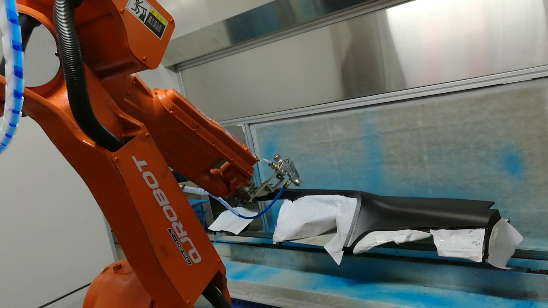
At about 00:13 in the video, the applicator is close to one section of the fixed instrument panel; the robot, tool, hoses, workpiece, and local white covering are visible together.
Planning robotic adhesive spraying for instrument panels by access
Path segmentation should begin with the real part and tool geometry. For each surface region, the study needs an approach direction, working orientation, clearance envelope, and an exit move. A region that looks continuous in a drawing may need two robot paths when a flange, steep change in curvature, fixture element, or hose posture limits access.
The recorded robot repeatedly approaches, follows a section, and retracts. For a new project, the exact split should come from an offline reach study followed by trials on representative parts. The goal is to keep the applicator in an appropriate working relationship to the specified path while avoiding awkward wrist posture and preventing the transition move from crossing the workpiece or fixture.
Treat lift-off and repositioning as part of the process
The moves between surface sections are not empty travel. They determine whether the tool clears the workpiece, whether the hose bundle has room to follow, and whether the next approach begins from a predictable posture. A useful motion plan defines where the applicator leaves a section, how far it withdraws, which joints change posture, and where the next controlled approach starts.
In the field sequence, the tool is visibly raised away between working sections. That observation supports reviewing transitions as explicit states. It does not reveal whether material flow is on or off at any instant, so the controls design must define and validate that relationship from the selected application equipment and process specification.
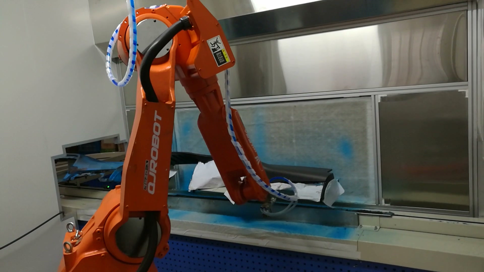
At about 00:37 in the video, after a visible withdrawal and repositioning phase, the applicator is near another section of the long instrument panel.
Keep fixture, covered areas, and services in the same clearance model
The workpiece is held at a fixed station, and white locally covered areas are visible. Their material and purpose are not established by the footage. In project planning, however, every fixture element, cover, temporary protection, and tolerance stack that can enter the tool envelope should be represented in the reach and collision study.
Service routing matters for the same reason. The applicator is connected by visible lines that move with the robot. The model should include bend limits, slack, snag points, and the most demanding wrist postures. A path that is clear for the metal tool body can still be unsuitable when the full service bundle is considered.
Define the interface states before optimizing motion
A robust sequence should distinguish part loaded and located, fixture ready, robot clear, applicator ready, path active, section complete, and robot withdrawn. The exact signals depend on the cell equipment. Separating the states makes interruptions easier to diagnose and gives the recovery plan a known starting point.
Recovery deserves its own trials. Consider a stop during approach, during a surface-following move, and during withdrawal. For each case, define the safe state, whether the current section may resume, and the permitted retreat path. This work should be agreed before trying to shorten transition time.
Plan the cell around the real application constraints
The blue enclosure and fixed station define the visible workspace, but the footage does not identify the enclosure’s ventilation or filtration design. A project review should use the adhesive supplier’s safety data, the application-equipment instructions, applicable local requirements, and a process risk assessment to determine ventilation, exposure controls, guarding, fire precautions, maintenance access, and waste handling.
Robot safeguarding also depends on the complete cell and operating modes. The assessment should cover loading, setup, cleaning, nozzle service, fault recovery, and access to the fixture as well as automatic motion. The final design must follow the applicable requirements for the installation location and the selected equipment.
Inputs for a useful feasibility study
| შეყვანის | Why it changes the concept |
|---|---|
| Representative part CAD and tolerances | Defines reachable surfaces, edge conditions, and clearance extremes |
| Required application zones and keep-out zones | Establishes where paths may begin, continue, and end |
| Adhesive and application-equipment data | Defines the process window and supporting equipment to validate |
| Fixture and local covering design | Adds real obstructions and repeatability conditions |
| Applicator, hoses, and dress package | Sets tool geometry, wrist loading, and service-routing limits |
| Cell layout and access modes | Shapes robot placement, guarding, maintenance, and recovery |
| მიღების მეთოდი | Connects trials to measurable project criteria |
A useful concept output includes a segmented path map, reach and posture study, tool and service-envelope model, interface-state sequence, safeguarding concept, recovery matrix, and trial plan. Performance commitments should follow representative-part testing with the agreed material and inspection method.
პრაქტიკული კითხვები დეტალური დიზაინის დაწყებამდე
Why split one instrument panel into several robot paths?
Different regions can require different approach directions and wrist postures. Explicit sections also create controlled places to lift away and reposition without crossing the part.
What should be included in the reach study?
Include the full part tolerance range, fixture, covers, applicator body, service bundle, robot wrist posture, approach and withdrawal moves, enclosure, and maintenance access.
How should keep-out areas be handled?
Define them from the part and process specification, represent them in the path model, and confirm them during trials. Visible white covering in this case should not be treated as proof of a specific masking method.
What should the acceptance plan measure?
Use criteria agreed for the actual adhesive, part, and downstream need. The plan may include path placement and process-result checks, but the exact measures and limits must come from the project specification rather than this video.
For a concept review, provide the part and fixture data, application zones, selected material and equipment information, layout, access needs, and proposed acceptance method. Request an EVST application review ან ელ sales@evsrobot.com.
Project acceptance follows the agreed project data, trial method, and records.