
By Уреднички тим EVST-а · Прегледао/ла Уреднички тим EVST-а · Last updated October 13, 2026 · Method: video companion · Уредничка политика · Политика исправки · Услови
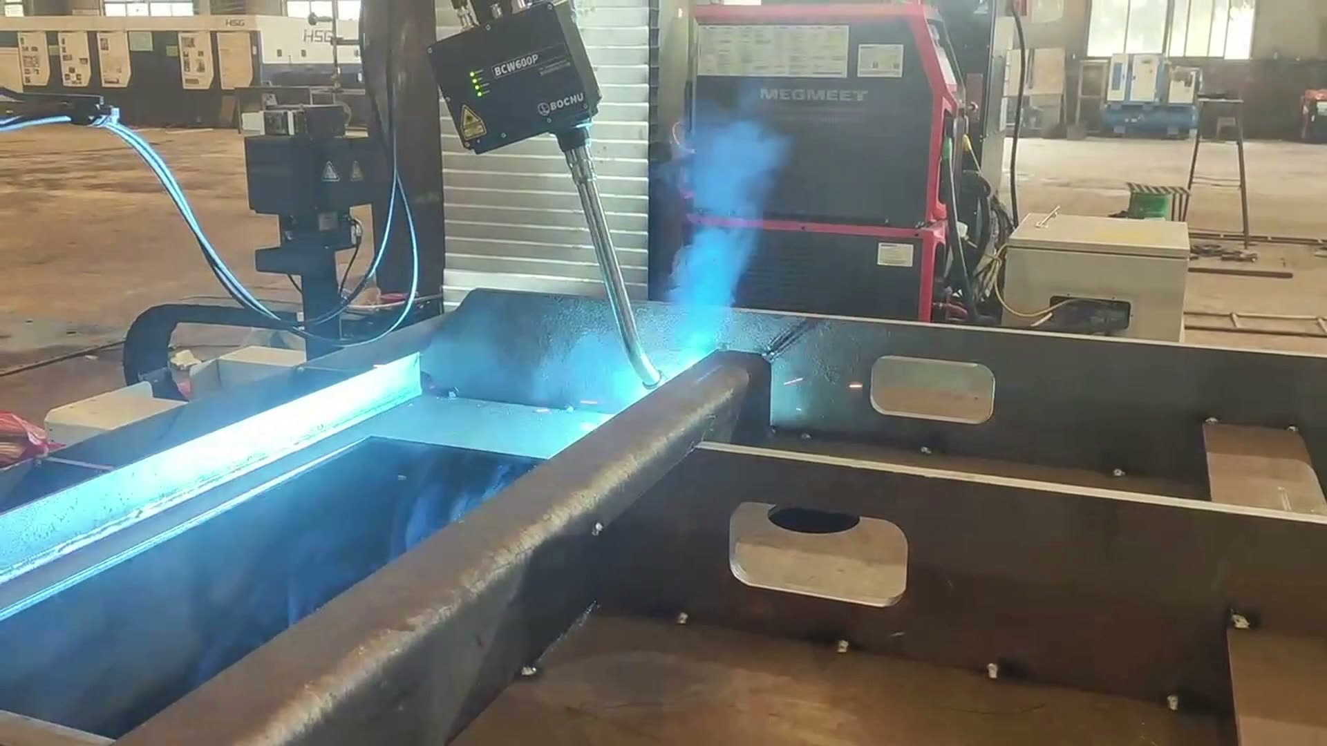
The recorded cell shows a robot torch travelling along a visible seam on a ribbed, box-shaped workpiece. The useful engineering question is therefore not what product the workpiece becomes, but whether its joint line, ribs and surrounding faces leave a repeatable path for the complete torch assembly. Material grade, final application, seam tracking, weld quality and production results are not established by the footage.
Assessing a similar joint? Send the part drawing, joint map and daily output за концепт ћелије и процену времена циклуса.
The visible path is simple; the surrounding geometry is not
From the wide view, the robot approaches a large box-like assembly with reinforcing ribs. Once the arc appears, the torch advances continuously along a straight visible joint while the camera moves closer. That sequence establishes robot welding and seam travel. It does not establish how the joint was located, whether sensing is present, or whether the resulting weld meets any acceptance standard.
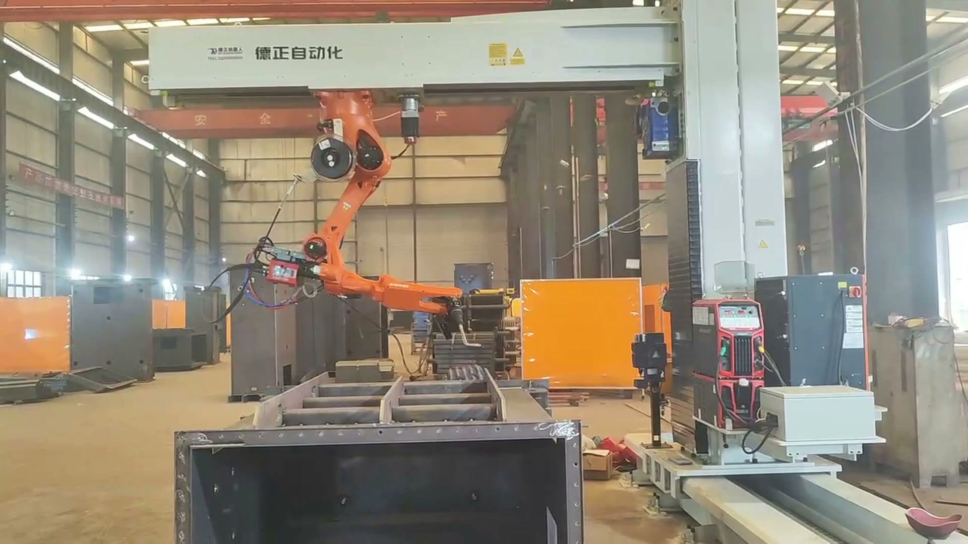
The ribs change the planning problem because a clear tool center point is only part of the envelope. The torch neck, nozzle, cable package, robot wrist and forearm also need clearance during approach, welding and withdrawal. A joint may be reachable at one static pose while the continuous route still forces the wrist or cable too close to a rib.
The ribs turn the joint line into a decision table
A robot seam-welding study should expand the nominal joint into a three-dimensional corridor. That corridor includes the required torch angle, the permitted stand-off range defined by the selected welding process, the approach and exit motions, and the volume occupied by nearby ribs. The design team can then separate three questions: Can the torch reach the joint? Can the complete arm follow it without interference? Can the fixture present the workpiece in the same relationship each cycle?
| Input to verify | Одлука коју подржава | What the footage does not prove |
|---|---|---|
| Joint map and access side | Robot position and route order | That every required seam is reachable |
| Rib and wall geometry | Torch angle and collision envelope | That the visible clearance covers all variants |
| Datum and clamping plan | How the programmed path relates to the part | Repeatability or distortion control |
| Welding procedure and acceptance method | Trial settings and inspection plan | Weld quality, penetration or compliance |
Four gates decide whether this joint is ready for programming
For a ribbed fabrication, the fixture has to locate the workpiece without covering the seam or occupying the torch corridor. Clamps also need a release sequence that does not allow the assembly to move unexpectedly after welding. If fit-up varies, the project team must decide how that variation will be controlled or detected; the video alone gives no basis for claiming automatic tracking or compensation.
- Geometry gate: prove the full torch and arm envelope through approach, seam travel and withdrawal.
- Datum gate: show that the fixture locates each supported variant without occupying the torch corridor.
- Process gate: define the approved welding procedure and the fit-up range it is intended to cover.
- Evidence gate: separate reduced-speed motion proof from representative weld trials and agreed inspection.
A joint advances only when all four gates have evidence. Exposed, repeatable seams with room around the ribs may pass quickly. A blocked torch posture, unstable datum, changing access side or fit-up outside the trial range sends the design back to layout, fixturing or process development. A successful-looking arc does not close any of those open items.
Turn the drawing review into a test plan
- Part drawings, joint locations and weld sequence.
- Available material and welding-procedure information.
- Rib geometry, access restrictions and allowable torch orientations.
- Part variants, fit-up range and fixture concept.
- Required inspection or acceptance method.
- Daily output, shift pattern and available cycle window.
These inputs should produce a short test matrix: the most restricted rib clearance, the longest required seam, the largest posture change, the extreme part variants and the agreed inspection method. Контактирајте EVST or email sales@evsrobot.com with the drawing package for a concept and cycle-time estimate.
The video documents a visible welding motion only. Product identity, material grade, sensing functions, weld quality and production performance require separate verification.