
Choose the camera layout only after listing the features that must be visible and the poses that reveal them. A fixed camera is a strong candidate when the robot or a stage can present every required feature repeatedly inside a practical field of view. A robot-mounted camera deserves evaluation when viewpoints must move around the part or enter a local viewing region. Neither choice is inherently more accurate: mounting rigidity, working distance, obstruction, lighting, calibration and the inspection method still determine whether the application can meet its acceptance criteria.
Start with a view list, not a camera bracket
Mark every feature that drives the decision: an outer edge, a recessed surface, a hole, a label, or a dimension between two features. For each one, record the viewing direction, allowable working-distance range, lighting access and anything that can hide it. This exposes the real architecture question. If the part can be reoriented so every required view reaches one stable imaging zone, moving the part past a fixed camera may be sufficient. If a required view remains hidden behind geometry or fixturing, moving the viewpoint may be worth the added integration work.
The difficult feature should be tested first. A layout that captures easy top surfaces but misses the one recessed edge used for acceptance has not reduced project risk.
What a fixed-camera layout asks the handling system to do
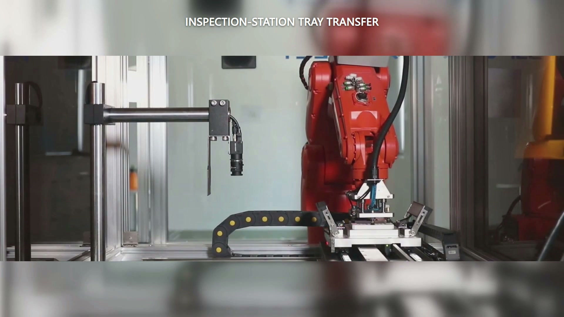
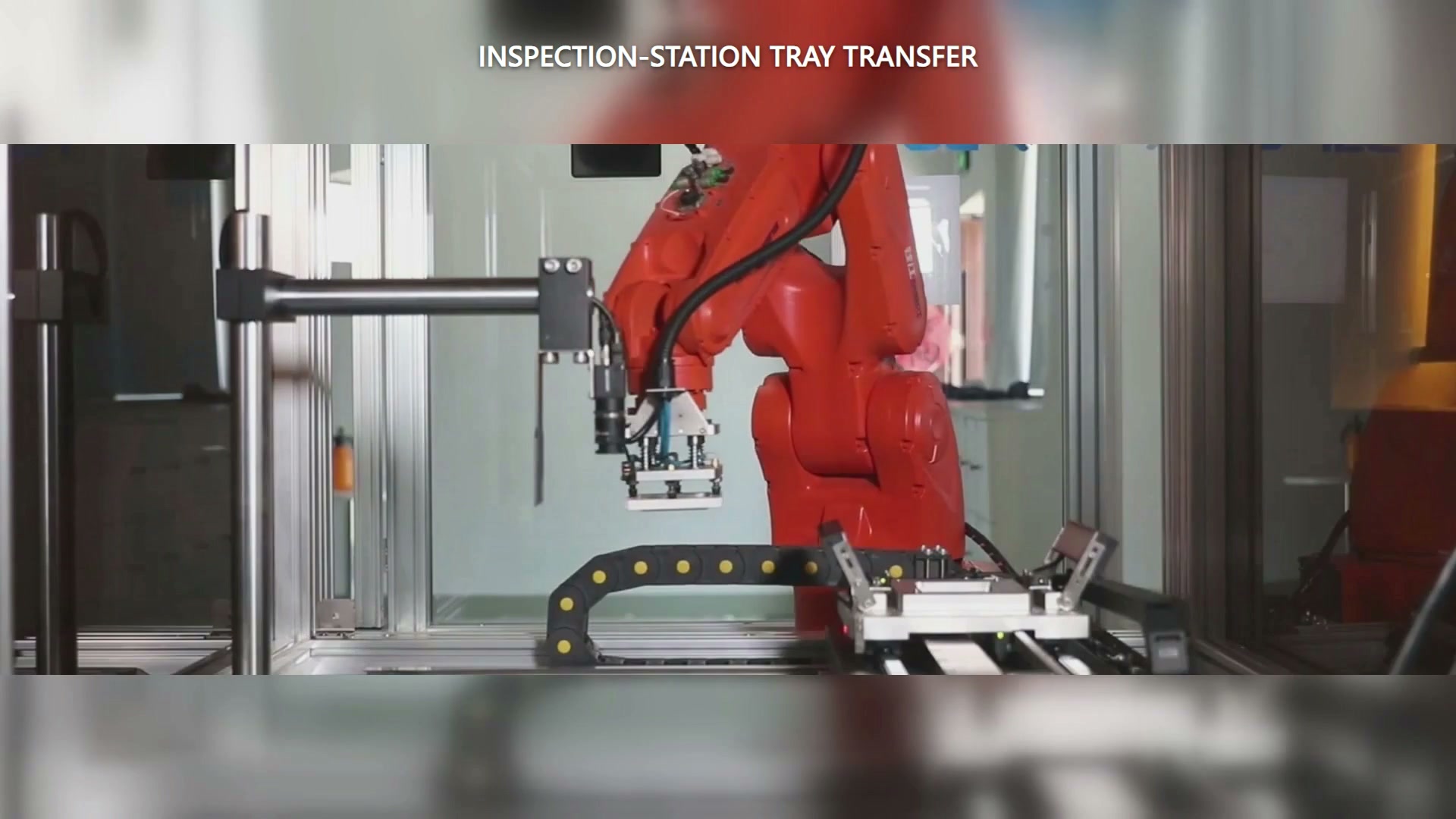
In the recorded case, a red industrial robot carries a white rectangular tray-like workpiece near a linear fixture. A camera is mounted separately at the side of the station and points downward; the device on the robot wrist is a handling tool, not a camera. The arrangement makes part presentation—not camera travel—the variable that exposes each required feature.
Official stationary-vision installation guidance calls for a rigid frame, a field of view that covers the target presentation area, and placement clear of the robot, end effector and carried part. Those points translate into a practical trial: present the part at every required pose, verify that the gripper and fixture do not hide the feature, and check that the complete moving envelope stays clear of the camera and its lighting.
The benefit is architectural simplicity only when part presentation is repeatable. If the robot must improvise many awkward orientations to compensate for one fixed view, the apparent simplicity has merely moved into handling and fixturing.
What changes when the camera moves with the robot
A wrist-mounted camera can bring the viewpoint to different sides of a part, but it shares the wrist envelope with the gripper and services. The same installation guidance notes the need for a rigid mounting stay, vibration control and clearance so the robot hand does not obstruct the field of view. A longer stand-off may solve one obstruction while creating another vibration or envelope concern, so the trade should be tested with the actual end effector.
The coordinate relationship also changes. Vision-guided robot documentation uses hand-eye calibration to relate camera and robot coordinates, with different motion arrangements for moving-camera and stationary-camera configurations. The trial plan therefore needs to state which coordinate relationship will be established and how it will be recovered after a mount or setup change.
Run one comparison around the hardest feature
Build two minimal concepts around the same part and acceptance requirement:
| Spørsmål | Fixed camera, moving part | Robot-mounted camera |
|---|---|---|
| Can every required feature enter the field of view? | Test all presentation poses | Test all robot viewpoints |
| What can obscure the image? | Gripper, fixture, neighboring equipment | Gripper, wrist hardware, services |
| What must stay rigid? | Camera and lighting frame | Wrist mount and camera support |
| What coordinate relationship is needed? | Camera to presentation/motion system | Camera to robot and part frame |
| What must be recovered after a change? | Presentation and camera setup | Mount, calibration and robot setup as applicable |
Compare missed views, re-presentation moves, clearance, calibration recovery steps and cycle interaction. Select the layout that obtains the required views with the simpler repeatable presentation and recovery sequence.
To review a real layout, send EVST a part photo or model, the feature locations, acceptance tolerances and the allowed ways to grip and reorient the part. Kontakt EVST to plan a two-layout feasibility trial around the hardest view.