Robotic Welding Cell Components & Integration: Power Source, Torch, Wire Feeder, Sensors (2026)
A robotic welding cell is built from seven functional subsystems: robot arm, welding power source, torch and consumables, wire feeder, positioner and fixture, peripheral sensors (seam tracking and vision), and safety enclosure. These subsystems connect through a standardised fieldbus layer (EtherCAT, DeviceNet, or PROFINET) combined with a welding-protocol layer such as ArcLink XT or Fronius RCU. Getting each component right, and integrating them in the correct sequence, determines whether a cell delivers repeatable weld quality or constant rework.
The Seven Subsystems at a Glance
Before examining each subsystem in depth, the table below provides a structural overview: the function each component performs, the brands most commonly specified, its approximate share of total cell cost, and the integration standard that governs its communication interface.
| Subsystem | Primary Function | Typical Brands | Cost Share % of Cell | Integration Standard |
|---|---|---|---|---|
| Robot Arm | Moves torch along programmed path with repeatability ±0.05–0.1 mm | FANUC, ABB, KUKA, Yaskawa, ESTUN, EVS Tech | 30–40% | EtherCAT / PROFINET fieldbus; ISO 10218-1 |
| Welding Power Source | Generates and controls welding arc (voltage, current, waveform) | Fronius, Lincoln, Miller, Panasonic, EWM, Aotai, Megmeet | 8–12% | ArcLink XT, Fronius RCU, DeviceNet / EtherCAT |
| Torch + Consumables | Delivers wire and shielding gas to weld pool; transfers current | Binzel, Tregaskiss, Fronius, Arctec, OTC | 3–6% | Torch body interface (Euro / Binzel taper) |
| Wire Feeder | Feeds solid or flux-core wire at controlled speed to torch | Lincoln, Fronius, Panasonic, OTC, Megmeet | 2–5% | Analogue / digital speed signal from power source |
| Positioner / Fixture | Holds and rotates workpiece for optimal welding position | Koike, Lincoln, EVST (EVS-SWP/DWP), Linde, custom | 10–25% | Coordinated motion (CDM) via robot controller fieldbus |
| Sensors | Seam tracking, joint-finding, gas-flow and temperature monitoring | Meta Vision MV, Servo-Robot, Scansonic, Keyence | 4–8% | EtherCAT / Ethernet; TAST via weld process signal |
| Safety Enclosure | Separates personnel from arc, UV, fume, and moving robot | Troax, Axelent, custom panel builders, integrator-supplied | 5–10% | ISO 10218-2, EN 14118, Category 4 light curtain / safety PLC |
Integration and commissioning labour typically adds 10–20% on top of hardware costs, rising toward the higher end when multi-vendor fieldbus gateways or complex coordinated-motion configurations are involved.
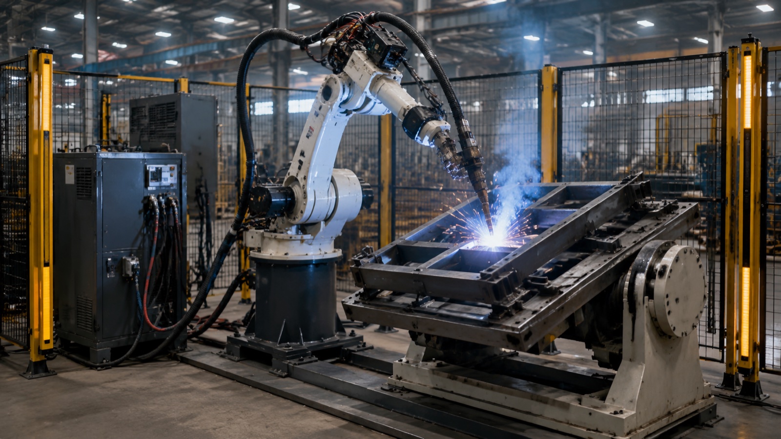
1. Robot Arm
The welding robot arm is the cell’s primary motion platform. For arc welding, a 6-axis configuration is standard: six rotary joints give the wrist sufficient freedom to approach fillet welds from any angle while maintaining torch perpendicularity to the joint. Seven-axis arms (with an extra swivel between shoulder and upper arm) are specified for thick-plate structural welding where the robot must reach around obstacles or maintain a consistent travel angle on curved surfaces without repositioning the positioner.
Payload Class and Reach
Arc welding torches (combined with cable management, wire conduit, and optional seam tracking hardware) typically load the robot wrist at 6–12 kg. Payload classes from 6 kg to 20 kg cover the vast majority of arc welding arms; heavier payloads up to 50 kg are specified when a water-cooled torch body, integrated seam tracking camera, and cable dressing hardware push the combined wrist mass above standard limits.
Reach is chosen by joint geometry. A 1,400 mm arm handles most single-fixture mid-size fabrications; 1,800 mm and 2,000 mm arms are common for structural frames and automotive chassis members where the robot must reach across a wide positioner without a linear track. When reach alone is insufficient, mounting the robot on a linear track extends coverage to multiple fixtures without adding a second robot.
Environmental Sealing
Welding environments generate spatter, metal fume, and flux dust. Sealed-motor variants (IP54 or higher on all motor housings) are specified when the robot arm sits close to the arc zone or when flux-cored wire is used. Cable management through hollow wrists reduces snag risk and simplifies conduit routing.
According to the International Federation of Robotics (IFR) World Robotics 2025 report, arc welding is the second-largest application segment for industrial robots globally, accounting for approximately 15 percent of new robot installations in 2024, with an installed base growing at around 8 percent annually. Several manufacturers have responded with welding-dedicated arm variants featuring sealed joints, hollow-wrist cable management, and H-suffix model designations optimised for continuous arc-on duty cycles.
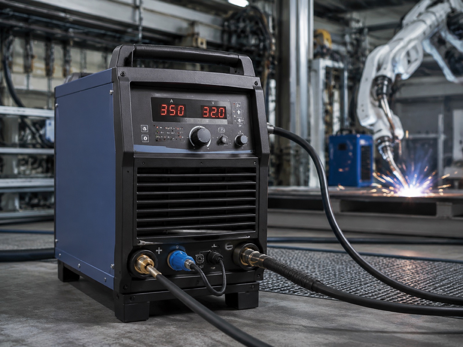
2. Welding Power Source
The welding power source converts plant power (three-phase AC) into a precisely regulated DC output at the arc. For MIG/MAG robotic welding, output ranges from 250 A at the low end (thin sheet, high-speed travel) to 500 A for thick structural steel sections requiring deep penetration.
Process Modes
Modern power sources for robotic applications support multiple waveform modes beyond basic constant-voltage MIG. Pulse MIG delivers precise droplet detachment at lower average heat input, preferred for aluminium and thin steel. Double-pulse (pulsed spray with a background pulse) creates the fish-scale bead appearance specified for cosmetic welds on stainless steel and aluminium. CMT (cold metal transfer, Fronius) uses wire retraction on each droplet transfer for very low spatter at thin gauges below 1.5 mm. TIG-DC is specified for high-purity tube welds in pharmaceutical and semiconductor fabrication.
Brand Landscape
Fronius (Austria), Lincoln Electric (USA), Miller Electric (USA), and Panasonic (Japan) are the reference brands for high-duty-cycle robotic installations. EWM (Germany) is often specified for aluminium and stainless steel where CMT or AC TIG modes are needed. Among Asian suppliers, Aotai and Megmeet have gained traction in price-sensitive markets; Megmeet’s Dex2 500MPR is listed as one of the compatible power sources in EVST’s EVS-AI welding system specification, alongside Aotai’s NBC500RP Plus.
Robot Interface
Every major power source brand publishes a certified robot interface package for the leading robot platforms. Fronius uses its RCU (robot control unit) protocol over EtherCAT; Lincoln ArcLink XT runs over DeviceNet or EtherCAT; Panasonic and Panasonic-interface power sources use proprietary digital protocols. Confirm the exact interface package version and firmware compatibility before purchasing. A mismatch between robot controller firmware and power source gateway firmware is one of the most common causes of commissioning delays.
According to Interact Analysis welding cell market data, the global robotic welding cell market was valued at approximately USD 6.8 billion in 2024 and is forecast to grow to USD 9.5 billion by 2029, driven by automotive EV programs demanding higher weld-quality consistency and the growing adoption of intelligent power sources with adaptive arc control in general fabrication.
3. Torch and Consumables
The welding torch carries current to the wire tip, directs shielding gas over the weld pool, and in robot installations must maintain geometry accurately enough that the TCP (tool centre point) stays within programming tolerance across thousands of production cycles.
Water-Cooled vs Air-Cooled
The decision threshold is approximately 300 A continuous duty cycle. Below that, air-cooled torches are simpler and lower in maintenance cost. Above 300 A, or in high-duty-cycle production (arc-on time above 60%), water-cooled torches prevent tip and nozzle overheating and extend consumable life significantly. Water-cooled systems add a cooler unit (typically mounted inside the cell or on the robot base) and water hoses through the cable dressing assembly.
Consumable Intervals
In practice, contact tips last 8–12 hours at moderate amperage; nozzles need cleaning or replacement every 4–8 hours depending on spatter accumulation; wire liners should be replaced every 3–6 months. Automated torch-cleaning stations (reamer, nozzle spray, wire cutter) extend consumable life by 30–50% by preventing spatter bridging and keeping shielding gas flow consistent.
TCP Accuracy
Robot torch positioning depends on the TCP being defined correctly and remaining stable. A bent or worn torch neck shifts the TCP by several millimetres, causing weld miss. Regular TCP verification against a reference pin (a 30-second routine at shift start) catches drift before it produces scrap.
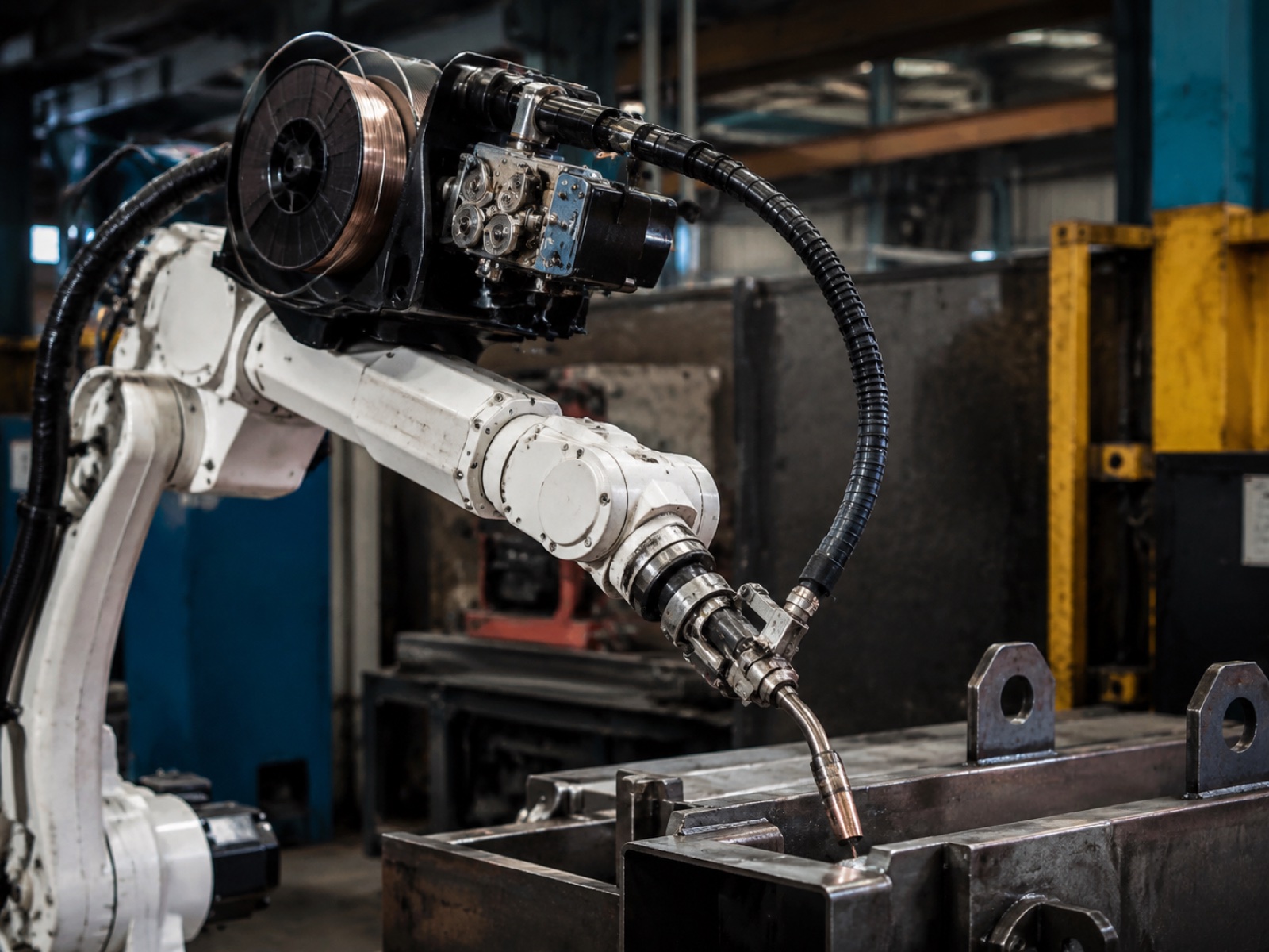
4. Wire Feeder
The wire feeder drives solid wire (or flux-cored wire) from a spool or bulk drum through a conduit to the torch contact tip. Feed rate is controlled by the power source in closed-loop with the arc voltage signal.
Drive Roll Configuration
Four-roll feeders (two drive rolls plus two pressure rolls) grip the wire more consistently than two-roll feeders, especially for soft aluminium wire or flux-cored wire with irregular outer surfaces. Four-roll configurations are standard in any application above 300 A or where wire diameter exceeds 1.2 mm.
Spool Size and Bulk Drums
Standard 15 kg and 20 kg spools are used on single-station cells with moderate output. High-production cells with long continuous run times often specify 200–300 litre bulk drums, which reduce spool changeover frequency from several times per shift to once per day or less. Bulk drums require a cabinet-mounted feeder rather than a robot-mounted configuration.
Robot-Mounted vs Remote Feeder
A robot-mounted feeder (attached to the robot’s upper arm or J3 link) keeps conduit length fixed across the robot’s working envelope, which stabilises wire-feed velocity. Remote feeders (pedestal or wall-mounted) are lighter on the robot and suit lower-duty-cycle applications, but conduit flex during large robot movements introduces feed resistance variation. For 24/7 production arcs, robot-mounted feeders are the preferred configuration despite their additional robot payload consumption.
5. Positioner and Fixture
The positioner holds and rotates the workpiece so the robot can access all weld joints from a favourable angle, ideally flat or horizontal-fillet position, which gives the best weld bead profile and lowest defect risk. Fixtures (tooling plates, clamps, and locating pins) hold the workpiece precisely in the positioner frame.
Positioner Types
Three main configurations cover most applications. Single-axis positioners (tilting or rotating) are the simplest, handling payload ranges of 200–1,000 kg and suiting symmetrical parts, pipe assemblies, and frames. Two-axis positioners (tilt-rotate or headstock-tailstock) give 360° rotation plus tilt, scaling from 200 kg to 3,000 kg, and are standard for structural sub-assemblies and automotive chassis. Three-axis variants offer full spatial orientation at 200–1,000 kg capacity, suited to complex weldments with joints in multiple planes.
The EVST EVS-SWP and EVS-DWP series cover single-axis and dual-axis configurations with payload capacity from 200 kg through 5,000 kg, coordinating with robotic arms via the cell controller for synchronised motion sequences.
Coordinated Motion (CDM)
In coordinated motion, the robot controller treats the positioner axes as additional external axes, synchronising their movement with the robot’s TCP path. This allows the robot to maintain a constant welding angle on a rotating workpiece without stopping motion, which is essential for circumferential welds on pipe flanges, pressure vessels, and rotating frames. Not all robot-positioner combinations support CDM natively; confirm that the positioner servo drive speaks the same fieldbus protocol as the robot controller and that the robot OEM provides a CDM licence for the axis count required.
6. Sensors: Seam Tracking, Vision, and Process Monitoring
Sensors separate a cell that produces repeatable quality from one requiring constant operator intervention. Three categories matter in most arc welding installations.
Laser Seam Tracking
A laser profilometer mounted ahead of the torch projects a structured-light line across the joint; a camera captures the reflected profile and software sends real-time corrections to the robot controller. This keeps the TCP on the joint even when fit-up variation or fixture wear shifts the seam by several millimetres. Leading systems include Meta Vision MV (EtherCAT interface), Servo-Robot (widely used in automotive structural welding), and Scansonic (preferred where the sensor must withstand high radiant energy near the arc). Seam tracking adds USD 8,000–20,000 to cell cost, but payback in reduced scrap is typically measured in weeks on any medium-to-high-volume application with variable fit-up.
Through-Arc Sensing (TAST)
TAST reads the arc current signal while the robot weave-oscillates across the joint: when the arc is centred, current is symmetric; deviation shifts the balance and the controller corrects the path. No additional hardware is required. TAST works well on structural-steel fillet welds but requires weaving, which constrains travel speed and is not suitable for autogenous or narrow-gap joints.
Vision and Process Monitoring
2D cameras handle fixture loading verification and rough joint-finding at cycle start. 3D vision (structured-light or time-of-flight) generates a point cloud and corrects the robot program for part-to-part variation, enabling path generation without manual teach-in. Gas-flow monitors check shielding gas delivery at the torch and trigger a weld-stop if flow drops below set point.
According to AWS (American Welding Society) industry data, porosity is the most commonly reported defect in robotic MIG/MAG production, and inadequate or intermittent shielding gas delivery is the primary root cause in approximately 40 percent of porosity cases. A gas-flow monitor with a weld-stop interlock addresses this failure mode at the process level rather than at the inspection stage.
7. Safety Enclosure
The safety enclosure physically separates personnel from the arc, UV radiation, weld spatter, and robot motion. It is a regulatory requirement under ISO 10218-2 (safety requirements for robot systems and integration), which mandates that all robot operating speeds and forces above prescribed thresholds be contained within a safeguarded space.
Enclosure and Light Curtain Standards
ISO 10218-2 requires a risk assessment that determines the required Performance Level (PL) for each safety function. For a welding robot operating at full speed in a fixed cell, the enclosure gate interlocks and any light curtains guarding operator access points are typically designed to PL d or PL e (Category 3 or Category 4 per ISO 13849-1). Category 4 light curtains, where a single component failure cannot lead to loss of the safety function, are the standard in automotive-supply cells and any installation audited to EN 14118 (detection of persons).
The safety-rated PLC (or safety module within the robot controller) monitors all safety inputs: gate switches, light curtains, and emergency stop chains. It commands the robot to a safe stop within the response time required by the risk assessment. Muting functions (temporarily bypassing a light curtain while a conveyor feeds parts into the cell) must be implemented with dual-channel interlocks and are a common audit finding when not correctly documented.
Fume Extraction Integration
Welding fume extraction is regulated under occupational health legislation (OSHA 29 CFR 1910.252 in the US; EN ISO 15012-4 in Europe). Torch-integrated extraction captures 70–90% of fume at source. The extraction unit should be interlocked with the robot controller (extraction active when welding is active, off when idle) and filter loading monitored by a differential pressure switch to avoid undetected filter saturation.
Integration Sequencing: Four Steps from Delivery to Production Arc
Integrating the seven subsystems follows a defined four-step commissioning sequence. Compressing or reordering these steps reliably generates rework.
| Step | Phase | Key Activities | Acceptance Criteria |
|---|---|---|---|
| 1 | Mechanical Installation | Robot base anchoring; positioner levelling; enclosure panel assembly; torch station and cooler mounting; cable management routing | Anchors torqued to spec; robot base flatness ≤0.1 mm/m; enclosure gapless; cable runs clear of robot envelope |
| 2 | Electrical and Fieldbus | Power source fieldbus gateway wiring; positioner axis registration; safety PLC I/O mapping; light curtain and gate interlock continuity; gas-flow monitor wiring | All fieldbus nodes recognised; safety function response time tested; I/O map signed off |
| 3 | Process Commissioning | TCP calibration; seam tracking calibration and offset validation; WPS trials and cross-section macros; coordinated motion path validation; torch-cleaning station cycle test | TCP repeatability ±0.1 mm; first-article macros meet ISO 5817 or AWS D1.1; seam tracking offset error <0.3 mm |
| 4 | Site Acceptance Test (SAT) | Production part run (20–50 cycles); dimensional and visual weld inspection; cycle time and uptime trial; customer sign-off | Zero critical defects in sample; cycle time within 5% of target; 4-hour uptime without unplanned stoppage |
In practice, aligning the seam tracking and robot controller coordinate systems on positioner-rotating welds accounts for 30–40% of process commissioning time in complex multi-vendor cells. Budget for this explicitly.
How Complete Cells Compare to Component-by-Component Builds
Buyers have two procurement routes: component-by-component integration (sourcing robot, power source, positioner, sensors, and enclosure separately) or a turnkey cell from a systems integrator or robot OEM.
Component builds offer flexibility and can reduce hardware cost by 5–15%, but they shift fieldbus integration, safety documentation, and process commissioning entirely to the buyer. Turnkey cells carry a premium but include pre-validated fieldbus configurations, safety documentation packs, and a defined SAT protocol. Integration labour (10–20% of total cost) is often lower on turnkey builds because the integrator has run the same configuration before.
Among the suppliers offering turnkey integrated cells, EVST pairs its welding robot arms with pre-integrated power sources (Aotai or Megmeet), the EVS-AI welding system for 3D vision and self-learning arc parameter management, and the EVS-SWP/EVS-DWP positioner series, covering single-station and multi-station layouts for customers across more than 100 countries. Differentiating factors buyers commonly evaluate alongside FANUC, ABB, KUKA, and Yaskawa offerings include IATF16949-certified manufacturing, CE/SGS/TUV third-party certification, field engineering dispatch capability, and a robotic platform that spans the full payload spectrum from collaborative welding arms to heavy-duty industrial configurations.
Related reading: MIG vs TIG vs Laser Robotic Welding (2026) | Complete Guide to Robotic Welding Automation (2026) | How to Build a Robotic Welding Cell: Layout Checklist | Robotic Welding in Automotive Manufacturing (2026) | Top 10 Welding Robot Brands (2026).
Frequently Asked Questions
Can I mix brands across robotic welding cell components?
Yes, multi-vendor cells are common. The critical requirement is fieldbus compatibility: the robot controller, power source, and positioner must share a common communication layer (EtherCAT, PROFINET, or DeviceNet). Confirm gateway availability before finalising your BOM and budget 15–25% extra on integration labour versus a single-vendor turnkey system.
How long does robotic welding cell integration typically take?
A standard single-station cell (one robot, one power source, single-axis positioner) typically takes 9–15 working days: mechanical installation 3–5 days, electrical and fieldbus wiring 2–3 days, process commissioning 3–5 days, and site acceptance testing 1–2 days. Multi-station cells with coordinated motion and 3D vision can run 4–8 weeks.
Is seam tracking a must-have or optional for welding robots?
Effectively mandatory for any application with fit-up variation above ±0.5 mm, which covers most fabricated steel assemblies and automotive sub-frames. Without it, fixture wear or part distortion shifts the joint beyond the robot’s TCP tolerance and produces off-seam welds. TAST is a low-cost entry point; laser profilometer tracking is preferred for aluminium or tight-tolerance work.
Does wire feeder placement affect weld quality in a robotic cell?
Yes. A robot-mounted feeder keeps conduit length fixed across the robot’s working envelope, stabilising wire feed velocity and reducing burn-back events. A remote pedestal feeder reduces robot payload demand but conduit flexing on large arm movements causes intermittent feed resistance. For 24/7 production arcs above 300 A, robot-mounted is the better choice.
How does fume extraction integrate into a robotic welding cell?
At two levels: torch-integrated extraction (nozzle or ring on the torch body) captures 70–90% of fume at source; ambient ventilation inside the enclosure handles the rest. Interlock the extraction unit with the robot controller so it runs only during welding, and monitor filter loading with a differential pressure switch to catch saturation before it affects air quality.
Outbound references:
American Welding Society (AWS) Standards |
ISO 10218-2: Safety of Robots: Robot Systems and Integration |
IFR World Robotics 2025 Report