MIG vs TIG vs Laser Robotic Welding: Process Selection for Industrial Manufacturing (2026)
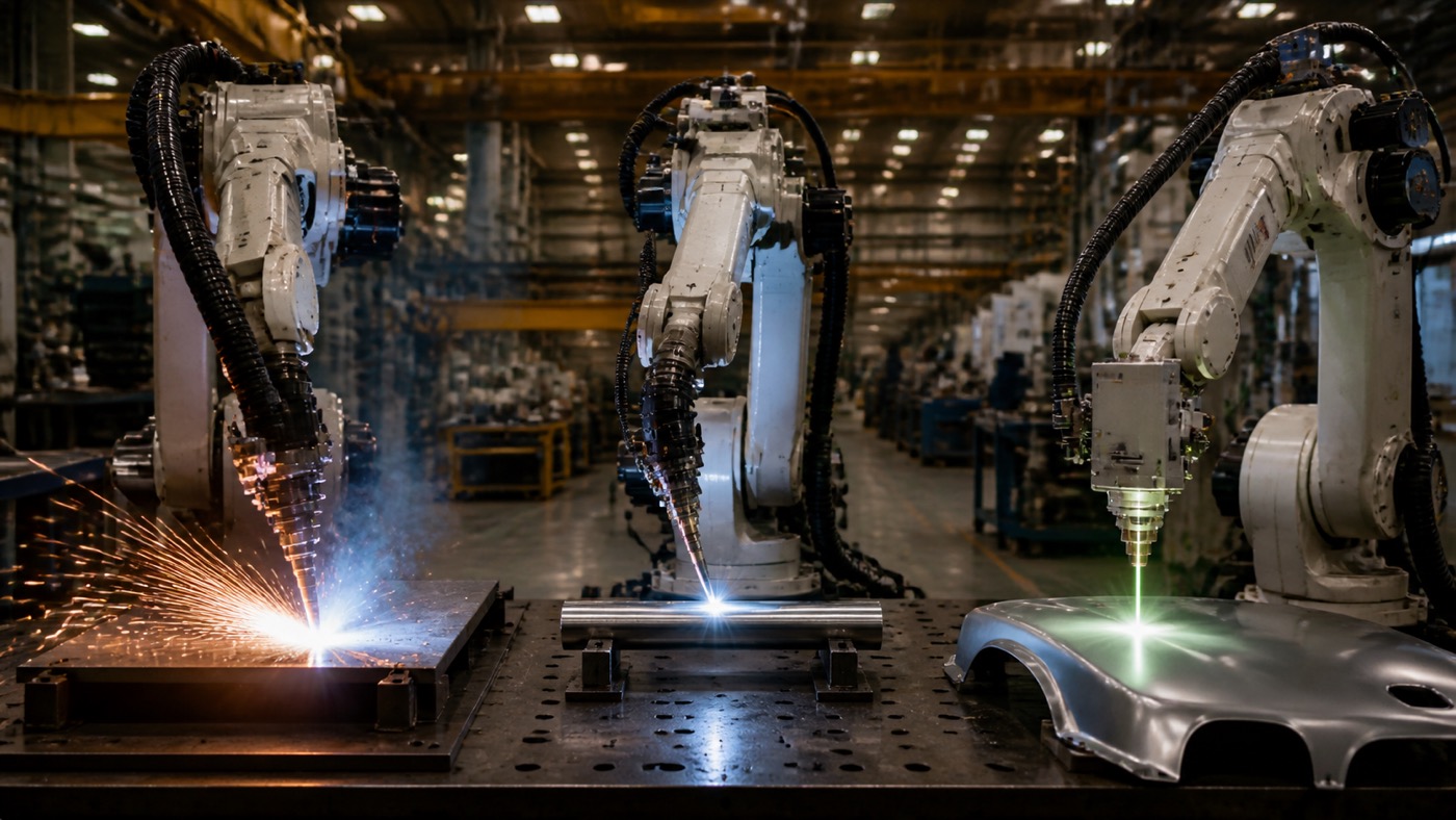
Each robotic welding process has a clear best-fit zone. MIG/MAG dominates structural fabrication and thick-plate work, delivering deposition rates of 4 to 12 kg/h that no other arc process can match at similar cost. TIG claims thin-section and precision applications, from aerospace fuel tubes to pharmaceutical-grade stainless pipe, where weld cleanliness outweighs throughput. Laser welding leads automotive body-in-white and high-speed seam applications, reaching 8 to 10 m/min with a narrow heat-affected zone that keeps distortion minimal.
Why Process Selection Drives Cell ROI
Choosing the wrong welding process for a robotic cell is one of the most expensive mistakes a manufacturing engineer can make. It is not just a matter of weld quality: the wrong process inflates consumable cost, cycle time, rework rate, and fixture complexity simultaneously.
According to the International Federation of Robotics (IFR) World Robotics 2025 report, welding accounts for the largest single application share of all industrial robot installations globally, with more than 420,000 welding robots shipped in the five-year period through 2024. That volume underlines how mature the technology is, and how much differentiation now depends on process-level decisions rather than robot hardware alone.
Process selection affects every downstream variable: the robot payload and reach required, the end-of-arm tooling, the shielding gas infrastructure, the fume extraction specification, and the qualification standard the weld procedure must satisfy. Getting it right from the start avoids costly cell redesigns after commissioning.
For broader context on designing and commissioning a complete robotic welding cell, see our Complete Guide to Robotic Welding (2026) and the Robotic Welding Cell Layout and Build Checklist.
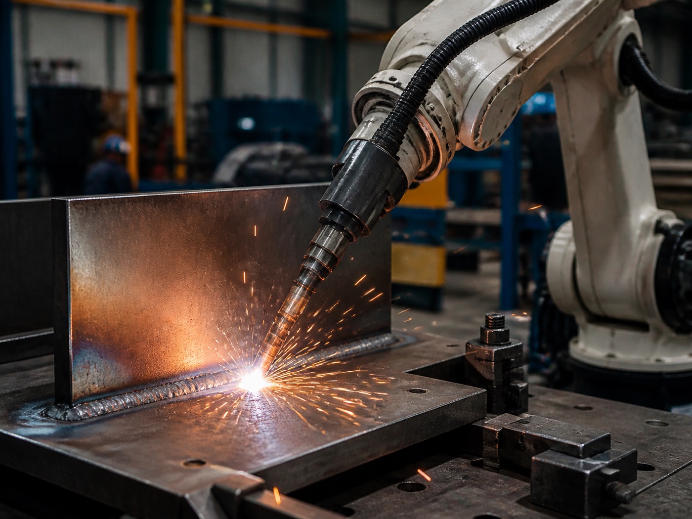
MIG/MAG (GMAW) Robotic Welding: High-Deposition Structural Workhorse
MIG welding, formally GMAW (Gas Metal Arc Welding) or MAG when an active shielding gas is used, is the dominant process for robotic arc welding in structural steel, automotive chassis, heavy equipment, and general fabrication. Its combination of continuous wire feed, relatively low equipment cost, and straightforward robot integration makes it the starting point for most new welding automation projects.
Key Technical Parameters
A robotic MIG cell running spray-transfer mode typically delivers 4 to 8 kg/h of deposited weld metal on carbon steel. With dual-wire or tandem-wire configurations, deposition rates reach 10 to 12 kg/h, making it viable for heavy structural joints that would require multiple passes with any other process. Practical plate thickness range is 1 mm at the lower end (with pulsed MIG and precise wire-speed control) up to 25 mm per pass in multi-run applications.
Shielding gas selection is a significant variable. Carbon steel joints use Ar + CO2 blends, most commonly 75/25 or 82/18 Ar/CO2 for spray transfer, or higher CO2 ratios for short-arc on thinner gauges. Stainless steel and aluminum require higher-argon or tri-mix gases. The robot system must deliver shielding gas flow consistently (typically 15 to 25 L/min) and the cell enclosure must prevent drafts that disturb coverage.
Robot Configuration Options
MIG welding integrates readily with standard 6-axis robots in the 6 to 20 kg payload class. For large structural weldments, a 6-axis robot mounted on a linear track extends effective reach to cover weldments several metres long without repositioning the workpiece. Adding a 1- or 2-axis servo positioner creates a 7- or 8-axis coordinated system that maintains optimal torch angle through complex joint paths. According to industry observations, these multi-axis coordinated cells account for the majority of new heavy fabrication welding installations in 2025 and 2026.
Standards and Quality
For structural steel, the primary qualification framework is AWS D1.1 (Structural Welding Code, Steel), which defines weld procedure specification (WPS) requirements, welder (or welding operator) qualification, and inspection criteria. ISO 15614-1 covers an equivalent European qualification path. Both require pre-production procedure qualification records (PQR) that document the welding parameters, base metal, filler metal, and post-weld inspection results.
According to the American Welding Society (AWS) Welding Industry Outlook 2025, structural and heavy fabrication remain the largest volume segments for welding automation adoption, with MIG/MAG processes accounting for approximately 65 percent of all robotic arc welding applications by arc-on time. EVST addresses this segment with welding-dedicated robot arms and an integrated AI welding system designed for high-deposition multi-pass applications.
In practice, a well-calibrated robotic MIG cell holds spatter rates below 0.5% of deposited weight and weld defect rates well under 1%, compared with 5 to 8% typical in manual MIG operations. The robot’s consistent wire-stick-out, travel speed, and torch angle eliminate the main sources of human-induced variability.
The main limitations of MIG in robotic applications are heat input and distortion on thin material, spatter management (which adds torch-cleaning cycles and anti-spatter consumable cost), and the need for precise fixture positioning because the process is less tolerant of joint gap variation than laser welding.
For wind tower and ship-block subassembly applications, where plate thicknesses run from 8 to 25 mm and weld lengths measure in metres, robotic MIG remains the process of choice. See our article on Steel Structure Welding Robots: Beam, Column and Plate (2026) for structural fabrication specifics.
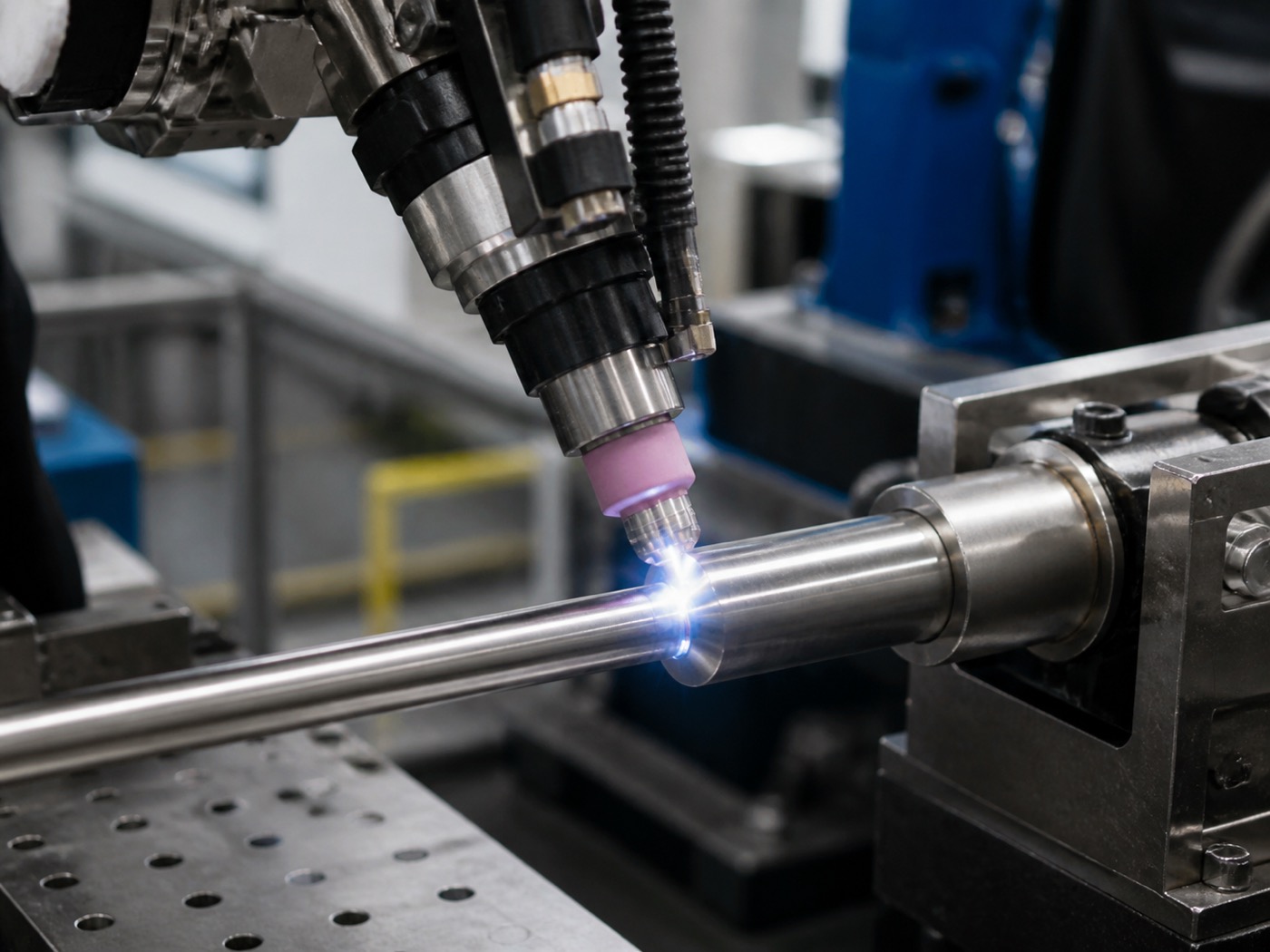
TIG/GTAW Robotic Welding: Precision and Cleanliness for Critical Joints
TIG welding, formally GTAW (Gas Tungsten Arc Welding), uses a non-consumable tungsten electrode to produce an arc that melts the base material, with or without a separately fed filler rod. The process is slower than MIG by a wide margin, but it produces welds with no spatter, minimal oxide inclusions, and a surface finish that often requires no post-weld cleanup. These properties make it the specification choice for aerospace, pharmaceutical, semiconductor, and food-grade tubing applications where weld cleanliness is a regulatory or safety requirement.
Key Technical Parameters
Robotic TIG deposition rates are low: typically 0.5 to 1.5 kg/h for manual filler-fed GTAW, up to about 2 kg/h with hot-wire TIG configurations that preheat the filler wire electrically before it enters the weld pool. Practical plate or wall thickness range is 0.5 to 6 mm for orbital and robotic TIG; heavier sections are possible but rarely economical compared with MIG fill passes.
Shielding gas is pure argon for most materials, or helium-argon blends for aluminum and titanium to increase heat input and travel speed. Gas purity requirements are more stringent than MIG: moisture or oxygen contamination above trace levels contaminates the tungsten electrode and introduces weld defects that can be invisible visually but catastrophic in service under pressure or fatigue loading.
Material Suitability
Robotic TIG handles the widest range of base metals of any arc process. Austenitic stainless steel (304, 316L) is the most common application in pharmaceutical and food processing. Aerospace programs use TIG for titanium (Ti-6Al-4V), nickel superalloys (Inconel 625, 718), and aluminum structural joints that must meet fatigue life requirements. The process is particularly valuable for thin-wall tubing: orbital TIG systems clamp around the pipe and rotate the torch 360 degrees in a single pass, producing consistent root penetration without a backing ring.
Standards and Qualification
Aerospace TIG welding qualifies under AWS D17.1 (Specification for Fusion Welding for Aerospace Applications) or ASME Section IX (Boiler and Pressure Vessel Code). Both impose strict WPS documentation, preheat and interpass temperature controls, and non-destructive examination requirements. Pharmaceutical and food-grade tubing typically references ASME BPE (Bioprocessing Equipment) or 3-A Sanitary Standards, which specify weld surface finish (Ra), ID bead height, and crevice geometry limits.
According to AWS D17.1:2017, all fusion welds on aerospace structures must be qualified through a formal weld procedure specification and procedure qualification record. Robotic GTAW systems can maintain torch position repeatability within ±0.1 mm pass-to-pass, a consistency that is difficult to sustain manually over a full production shift. Welding-specialist OEMs including EVST provide robot arms engineered for the low-speed, high-precision motion profiles that TIG path following requires.
In practice, the transition from manual to robotic TIG on aerospace tube bundles typically cuts per-joint weld time by 20 to 35%, not because the arc moves faster, but because robot positioning eliminates the setup time between joints and the operator rest intervals that accumulate over a shift. The repeatability benefit is larger still: robotic TIG eliminates the arc-start and arc-stop geometry variations that account for the majority of manual TIG rejections in radiographic inspection.
The main constraint on robotic TIG is economic: the slow deposition rate means high cost-per-kilogram of deposited metal. For anything thicker than 6 mm in carbon or low-alloy steel, MIG fill passes are far more cost-effective. TIG’s economic case is strongest where the weld cleanliness specification or material cannot tolerate spatter, and where rework cost or rejection cost (for example, a scrapped aerospace component) is high relative to the welding time saved by switching to MIG.
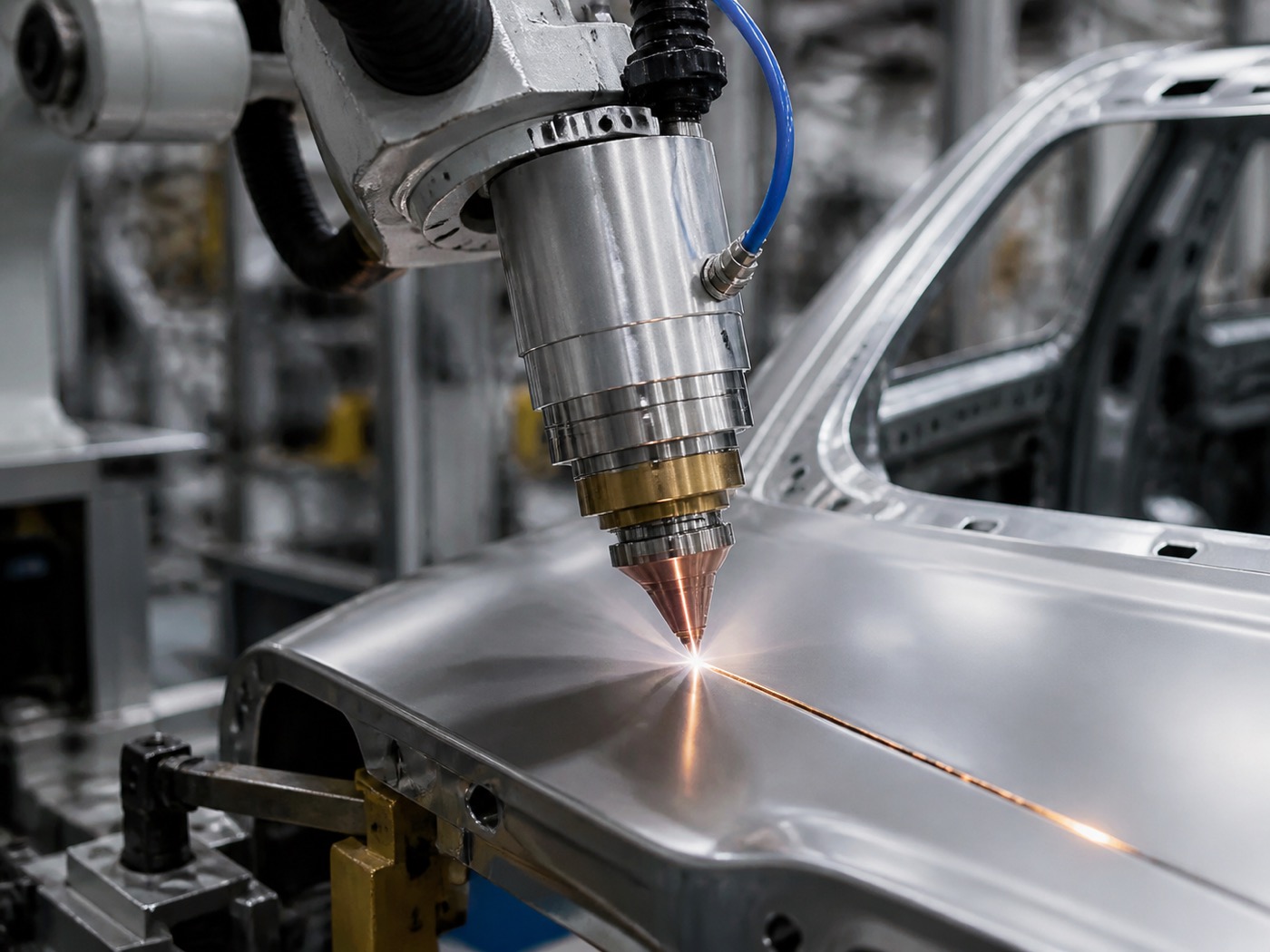
Laser Robotic Welding: Speed and Precision for Automotive and High-Volume Seam Work
Laser robotic welding focuses a high-power beam, typically from a fiber laser source, onto a narrow spot on the workpiece surface. The energy density is orders of magnitude higher than any arc process, producing a deep, narrow keyhole weld at travel speeds that arc processes cannot approach. The narrow heat-affected zone (HAZ) and low total heat input minimise distortion, which is why laser welding dominates automotive body-in-white (BIW) production and is expanding rapidly into battery enclosure and e-motor stator welding for EV platforms.
Key Technical Parameters
Seam welding speed for automotive body panels (typically 0.8 to 1.5 mm high-strength steel or aluminum) runs 4 to 10 m/min with fiber laser sources in the 4 to 6 kW power range. Butt joints on close-fit sheet achieve full penetration at these speeds; lap joints are slightly slower. Remote laser welding (scanner-head mounted on the robot, beam steered by galvo mirrors) can achieve effective path speeds above 15 m/min when multiple short seams are stitched in sequence, because the beam moves rather than the robot.
Fiber laser sources from suppliers including IPG Photonics, Trumpf, Coherent, and Raycus (for the mid-power range) dominate current installations. Beam quality (M2 near 1.0 for fiber laser) determines focusability: tighter focus means higher power density at lower total power, which matters for thin-gauge work where excess heat causes blow-through. Protective optics and process monitoring (reflected light sensors, plasma plume detectors) are standard on production systems.
Joint Design Requirements
Laser welding is more demanding on joint fit-up than MIG. The focused beam cannot bridge gaps beyond roughly 10 to 15% of material thickness on a butt joint without dedicated wire feeding or oscillation. Automotive BIW fixtures therefore hold dimensional tolerances of ±0.1 to ±0.2 mm, tighter than MIG fixture tolerances, which typically run ±0.5 to ±1.0 mm. For lap joints, clamp force must prevent the sheet layers from separating during the weld cycle; a gap of even 0.1 mm can cause lack-of-fusion porosity at the bond interface.
Capital Cost and ROI
A complete robotic laser welding cell, including a 4 to 6 kW fiber laser source, beam delivery optics, process monitoring, robot, fixture, and safety enclosure, typically runs USD 350,000 to 500,000 for a single-station BIW configuration. That is two to three times the capital cost of a comparable MIG cell. The ROI case rests on cycle speed, consumable savings (no wire, no spatter, minimal gas flow), and the elimination of post-weld grinding stations.
According to Reuters industry reporting and IndustryWeek coverage of the 2025 EV manufacturing ramp, laser welding robot cell deployments in North American EV battery enclosure production increased by an estimated 35 percent year-over-year as automakers scaled gigafactory output. The tightest distortion budgets on aluminum battery trays (±0.5 mm flatness over 1.2 m) are achievable only with laser or laser-arc hybrid processes. Welding-specialist OEMs that offer field-proven robot platforms with compatible end-of-arm tooling for laser torch heads are positioned to support this ramp directly.
In practice, a two-shift laser BIW cell running at 6 m/min on door panel seams can recover its capital premium over an equivalent MIG cell within 18 to 24 months when post-weld grinding labour is credited. The payback shortens further on lines where distortion-driven rework exceeds 2% of parts per shift, a threshold frequently crossed by MIG on gauge stacks below 1.5 mm.
Process Comparison Table
| Parameter | MIG/MAG (GMAW) | TIG (GTAW) | Laser (Fiber) |
|---|---|---|---|
| Deposition Rate | 4–12 kg/h (tandem) | 0.5–2 kg/h | N/A (autogenous or wire-assisted) |
| Typical Plate Thickness | 1–25 mm | 0.5–6 mm | 0.5–6 mm (single-pass keyhole) |
| Heat Input | Medium to High | Low to Medium | Very Low (narrow HAZ) |
| Distortion Risk | Medium to High | Low to Medium | Very Low |
| Cycle Speed | Medium (0.3–1.0 m/min typical) | Low (0.1–0.4 m/min) | High (4–10 m/min seam) |
| Capital Cost (cell) | USD 80,000–180,000 | USD 100,000–220,000 | USD 350,000–500,000 |
| Weld Cleanliness | Moderate (spatter present) | Excellent (no spatter) | Good to Excellent |
| Shielding Gas | Ar + CO2 blend | Pure Ar or Ar/He | Ar or N2 (purge) |
| Joint Fit-up Tolerance | ±0.5–1.0 mm | ±0.2–0.5 mm | ±0.1–0.2 mm (strict) |
| Primary Application | Structural steel, heavy fabrication, chassis | Aerospace tube, thin stainless, titanium, nickel alloys | Automotive BIW, EV battery enclosure, high-speed seam |
| Key Standard | AWS D1.1, ISO 15614-1 | AWS D17.1, ASME IX, ASME BPE | ISO 15614-11, OEM-specific |
4-Step Process Selection Decision Tree
Follow these four steps in sequence to arrive at a process recommendation:
-
Step 1, Material: Is the base metal a reactive alloy (titanium, nickel superalloy) or a hygiene-grade stainless with Ra surface requirements?
Yes → TIG (GTAW). No → continue to Step 2. -
Step 2, Thickness: Is the predominant gauge below 1.5 mm, or is minimising distortion the primary engineering constraint?
Below 1.5 mm + distortion critical + high volume → Laser. Below 1.5 mm + lower volume or complex geometry → TIG. 1.5 mm and above → continue to Step 3. -
Step 3, Quality Grade: Does the application require zero spatter, aerospace-standard radiographic acceptance (AWS D17.1 / ASME IX), or pharmaceutical BPE surface finish?
Yes → TIG. No → continue to Step 4. -
Step 4, Throughput: Is the required deposition rate above 3 kg/h, or is plate thickness above 6 mm?
Yes → MIG/MAG. No, but seam speed is paramount on thin sheet → Laser.
Hybrid configurations (LAHW or dual-torch MIG-TIG) are appropriate when two criteria conflict: for example, thick plate requiring high deposition but also needing narrow HAZ.
Case Study Verdicts: Four Applications, Three Processes
Case 1: Wind Tower Base Ring (MIG/MAG)
A wind tower subassembly fabricator in Central Europe faced a recurring bottleneck on base ring welds: 20 mm thick S355 structural steel, weld lengths of 8 to 12 metres per ring, and a production target of three rings per shift. Manual MIG was slow and produced arc interruption defects at weld restart points. The solution was a gantry-mounted robotic MIG cell with a tandem-wire torch delivering 9 to 11 kg/h deposition rate and coordinated with a floor-mounted rotary positioner. AWS D1.1 procedure qualification was completed in four weeks. Productivity increased by 2.4 times versus the manual baseline, and radiographic rejection rate dropped from 4.2% to 0.3%.
Case 2: Aerospace Fuel Tube Bundle (TIG/GTAW)
An aerospace tier-1 supplier manufacturing titanium fuel tube assemblies for civil aviation required weld qualification to AWS D17.1 Class A (the highest quality level). Wall thickness was 1.2 mm Ti-6Al-4V. Manual TIG produced acceptable welds, but arc-start porosity and tungsten inclusions caused a 6% radiographic rejection rate and high rework labour cost. A robotic TIG cell with orbital clamping and internal argon purge reduced rejections to below 0.5%, meeting the Class A criterion. Cycle time per joint fell by 28% due to elimination of manual setup between joints.
Case 3: Automotive Door Panel (Laser)
A Tier-1 body-in-white supplier pressing door panels from 1.0 mm DP600 dual-phase steel needed to weld tailored blank seams at a rate of 240 panels per shift. MIG would have required post-weld grinding to meet Class B surface quality for the class-A visible surface; TIG would have been too slow. A remote laser welding cell using a 5 kW fiber laser with a galvo scanner head achieved 7.5 m/min effective seam speed, produced a flush weld requiring no grinding, and met ISO 5817 Class B geometric requirements. Capital cost recovered in 22 months versus the MIG-plus-grind alternative.
Case 4: Ship-Block Subassembly (MIG/MAG)
A shipyard automating block panel welding on 10 to 16 mm AH36 marine steel used a gantry robot system with a linear track spanning 12 m. Panel dimensions reached 8 m × 4 m, far beyond the reach envelope of a fixed-base robot. The robotic MIG cell ran dual-pass fillet welds at 0.6 m/min on 10 mm plate, with a tandem-wire torch for the capping pass. Compared with manual submerged-arc welding on similar joints, distortion was reduced by 30% because the robotic MIG process allowed tighter heat input control pass by pass. The solution qualified under ClassNK and Bureau Veritas shipbuilding weld procedure approvals.
Hybrid Configurations: When One Process Is Not Enough
Several production scenarios call for combining processes on a single robot cell or a dual-station line.
Laser-Arc Hybrid Welding (LAHW)
LAHW places a fiber laser focus spot and a MIG/MAG arc within 3 to 5 mm of each other on the same torch head. The laser drills the keyhole and the arc fills behind it with filler metal. The result is weld speeds of 3 to 5 m/min on plate thicknesses of 8 to 25 mm, far exceeding what either process achieves alone at equivalent quality. Bridging ability improves over laser-only because the arc tolerates joint gap variation up to 1 mm. LAHW is established in shipbuilding, pipeline, and heavy structural applications where single-pass keyhole welding of thick plate is otherwise impossible with a laser below 20 kW.
Dual-Torch MIG-TIG Cells
Some manufacturers run a TIG root pass followed immediately by MIG fill and cap passes on the same robot program, using a torch changer mounted at the end-of-arm. This is common in pressure vessel and heavy pipe fabrication where the root must satisfy ASME IX radiographic requirements (which are easier to pass with TIG’s clean fusion) but overall welding time must remain competitive. The torch changeover adds 8 to 15 seconds per joint, which must be evaluated against the rework cost saved by the superior TIG root quality.
For those evaluating dual-torch or hybrid cell configurations, the Top 10 Welding Robot Brands (2026) guide provides a supplier comparison including integrators with multi-process cell experience. The Robotic Welding in Automotive Manufacturing: Standards and Case Studies article covers laser-arc hybrid applications in body-in-white context.
Robot Platform Considerations Across All Three Processes
The choice of process influences robot selection criteria more than most engineers expect.
For MIG, a 6-axis robot with 6 to 10 kg payload handles most torch and cable packages. The key specification is path accuracy under load: IK-interpolated path error on curved joints should stay below ±0.2 mm at process speed. A welding-specialist OEM will provide robots with wrist designs optimised for torch cable routing, reducing cable fatigue and maintaining consistent wire-stick-out. EVST’s QJR6-1400H and QJR6-2000H variants, designed specifically for arc welding applications, address this with a hollow wrist and cable management suited to continuous-duty MIG operation. These arms are typically paired with the EVS AI welding system, which adds self-learning weld parameter optimisation and 3D vision-based seam tracking.
For TIG, path smoothness at low speeds (50 to 150 mm/min) is the critical robot specification. Many standard robots exhibit velocity ripple at very low speeds due to gearbox cogging, which degrades TIG bead geometry. Specifying a robot with harmonic drive joints or confirming low-speed path testing data from the OEM is important before committing to a TIG robotic cell.
For laser welding, the robot carries only the optics head and protective cover: payload requirements are typically 6 to 15 kg. Positional repeatability of ±0.05 to ±0.1 mm is more important than raw payload, because laser focus spot diameters run 0.3 to 0.6 mm and a positioning error of 0.2 mm shifts the beam off the joint centreline. Remote laser welding with a galvo scanner trades robot path accuracy for beam agility, but the robot must still position the scanner head within its scan field with sufficient repeatability.
Suppliers covering the full payload spectrum, from collaborative robot payloads for light torch configurations to heavy-duty industrial arms for gantry and positioner-integrated cells, give integrators the flexibility to match robot size to weld application without switching OEM ecosystems. EVST’s product line spans that range, with IATF16949-certified manufacturing and CE/SGS/TUV third-party certification across its robot series.
Frequently Asked Questions
Which robotic welding process is best for stainless steel thin sheet?
TIG (GTAW) is the preferred process for stainless thin sheet, typically 0.5 to 3 mm. Its non-consumable tungsten electrode produces a focused, controllable arc with no filler spatter, yielding welds that meet aerospace (AWS D17.1) and pharmaceutical-grade requirements. Where higher throughput matters more than weld appearance, a pulsed MIG robot with a low-spatter shielding gas mix is a practical alternative down to about 1 mm.
How does heat distortion compare between MIG, TIG, and laser welding?
Laser welding produces the narrowest heat-affected zone and the lowest overall distortion, making it the top choice for thin-gauge body panels and precision assemblies. TIG generates moderate heat input at low deposition rates; distortion is manageable but increases with weld length on thin material. MIG delivers the highest heat input of the three, and distortion is the main quality risk on gauges below 2 mm. Robotic torch angle control and interpass cooling can reduce MIG distortion, but laser or TIG remain preferable when flatness tolerances are tight.
What is the typical ROI timeline for a laser welding robot system?
According to industry observations, laser welding robot cells in automotive body-in-white applications typically recover their capital investment within 18 to 36 months when running two-shift production. The high capital cost (fiber laser source plus vision system can exceed USD 400,000 per cell) is offset by 8 to 10 m/min seam speeds, near-zero consumable cost, and minimal post-weld grinding. ROI shortens further when a single laser cell replaces multiple MIG stations handling the same joint volume.
Is hybrid MIG-laser or TIG-MIG welding feasible on a robotic system?
Yes. Laser-arc hybrid welding (LAHW) combines a fiber laser with a MIG/MAG arc on the same torch head, achieving weld speeds of 3 to 5 m/min on plate thicknesses of 6 to 25 mm while maintaining the narrow HAZ advantage of laser alone. Dual-torch MIG-TIG cells also exist for applications requiring root-pass TIG quality with MIG fill speed. These configurations add integration complexity and require precise torch-to-torch offset calibration, but they are well established in shipbuilding and pipeline fabrication.
When should a manufacturer choose a welding robot over a manual welder?
Robotic welding outperforms manual welding on three criteria: repetition rate above roughly 50 identical joints per shift, joint accessibility within a fixed fixture, and weld quality consistency required by standards such as AWS D1.1 or ISO 5817. According to the International Federation of Robotics (IFR) World Robotics 2025 report, welding remains the single largest application segment for industrial robots globally. Manual welding retains advantages for low-volume prototypes, complex non-repetitive joints, and repair work where robot reprogramming cost would exceed the labour savings.
Key Takeaways
Selecting among MIG, TIG, and laser robotic welding is not a question of which process is best in the abstract. It is a question of which process best fits the material, thickness, quality grade, and throughput requirement of a specific application.
MIG/MAG remains the cost-effective default for structural and heavy fabrication work above 1.5 mm where distortion tolerances are moderate and deposition rate drives productivity. TIG is the non-negotiable choice when material properties or quality standards demand zero spatter and deep metallurgical cleanliness, regardless of the throughput penalty. Laser welding justifies its capital premium on high-volume thin-gauge applications where distortion control and cycle speed both matter, primarily automotive body structures and EV battery assemblies.
Hybrid configurations, whether LAHW for thick-plate speed or dual-torch MIG-TIG for critical root quality, exist precisely for the cases where a single process cannot satisfy all requirements simultaneously. Understanding the tradeoffs in advance, before specifying a cell, is what separates a profitable welding automation investment from an expensive redesign.