
By Συντακτική Ομάδα EVST · Αξιολογήθηκε από Συντακτική Ομάδα EVST · Ενημερώθηκε στις 16 Οκτωβρίου 2026
Μέθοδος: ανάλυση βίντεο περίπτωσης και αναφορές μηχανικής · Πολιτική σύνταξης · Πολιτική διορθώσεων · Όροι
A laptop keyboard housing combines broad flat regions, a perimeter, a large opening and a dense field of smaller openings. A useful robot grinding path cannot treat that geometry as one uniform plane. It must divide the housing into surface zones, select a tool posture for each zone, and connect those passes without letting the abrasive disc bridge an edge, enter an opening or collide with the fixture.
Discuss your housing-finishing application with a part model, target areas and acceptance method.
Read the part as a set of contact conditions
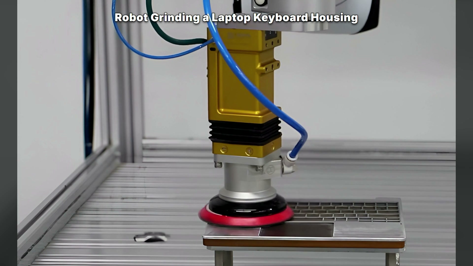
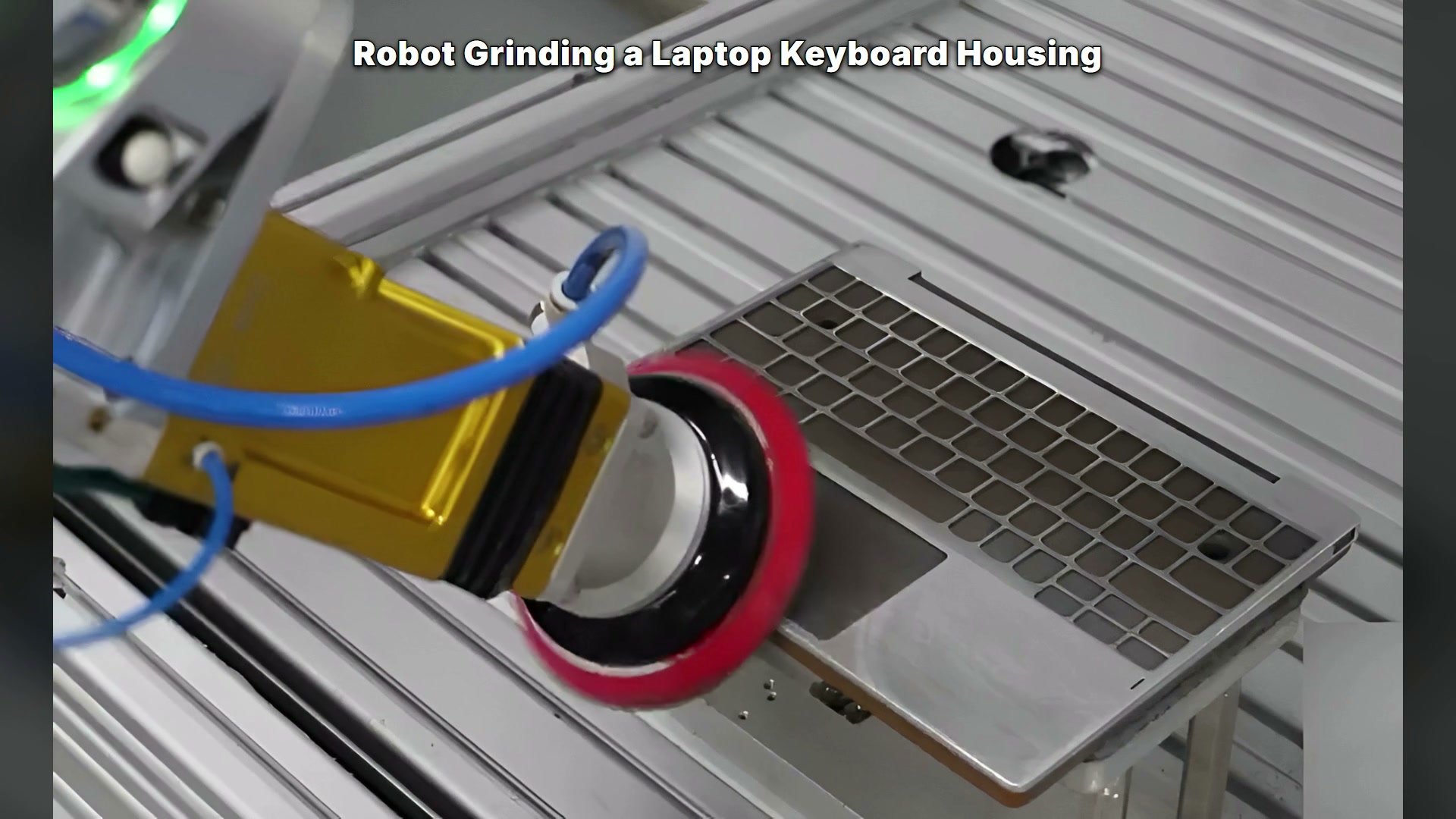
The case video begins with a close view of a circular abrasive tool working across the housing. The part includes a large rectangular opening and many smaller openings, so the available contact area changes continually. Later views reveal the robot, tool assembly, fixed housing and enclosure, followed by angled approaches to other regions.
This sequence points to a planning problem: the center of a broad panel, the strip beside an opening and the outer perimeter do not present the same support beneath the disc. A path that is stable on a wide surface may bridge an opening or concentrate contact near an edge. The program should therefore identify where full-face contact is possible, where overlap must be reduced, and where a separate edge strategy is required.
Build coverage from zones, not one continuous raster
Start by marking the areas that require treatment and the areas that must remain untouched. Divide the working surface into broad fields, narrow lands between openings, perimeter bands and corner transitions. Then assign a pass direction and approach posture to each zone.
A broad field can support overlapping passes. Near an opening, the path should preserve enough supported tool face to avoid dropping into the void. At the perimeter, the planner must decide whether the tool stops before the edge, follows it with a controlled offset, or uses a separate operation. Those decisions depend on the actual abrasive, compliance mechanism, part material and finish specification; the video does not establish them.
The benefit of zoning is not more program points. It is a reviewable reason for every change in tool angle and path direction.
Tool orientation changes the effective contact patch
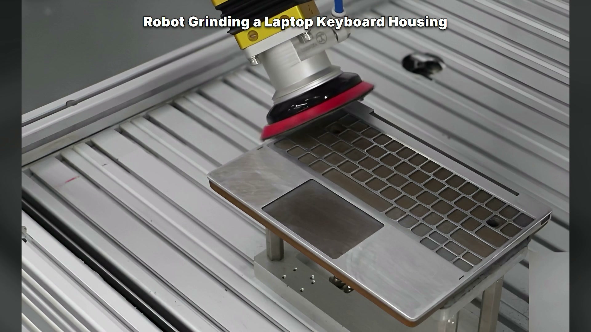
The footage shows the robot tilting the disc as it approaches different housing regions. That visible change matters because disc orientation affects which portion of the abrasive face contacts the part and how much clearance remains around openings and fixture elements.
An engineering trial should inspect the entire tool assembly rather than the nominal tool center point. The abrasive face, backing pad, spindle body, compliance unit, hoses and robot wrist all need clearance. A safe-looking tool point can still place the backing pad over an opening or bring the spindle close to the fixture. EVST’s grinding and polishing workstation guide shows why tool configuration, dust handling and maintenance access belong in the same cell review.
For offline review, model the real tool dimensions and the worn-tool condition. On the floor, use representative housings and inspect each transition at reduced speed before running the complete cycle. The purpose is to confirm supported contact and clearance, not to infer force or finish from robot motion.
Transitions deserve their own acceptance criteria
Coverage failures often appear between zones. The robot may lift too late after a broad pass, rotate the wrist while the disc still contacts the surface, or re-enter near an opening with an unstable contact patch. These events can be short, yet they determine whether the final result is consistent.
Write transitions into the process plan: approach, establish contact, traverse, leave contact, reorient and move to the next zone. Review where the disc is supported during each step. If the application uses a compliance device or force-control function, validate its limits with the actual stack-up and process settings rather than assuming the hardware appearance proves the function. ATI’s robotic deburring tool manual is a useful external example of how approach direction and compliant travel become explicit programming constraints; it does not identify the hardware shown here.
Dust and debris also influence the cell design. Collection points, airflow and maintenance access should be assessed for the selected abrasive process and material. The cropped footage shows an enclosure, but it cannot verify dust-control performance.
What to measure in a representative trial
A trial should use housings that reflect real dimensional and flatness variation. Mark the required treatment zones and compare them with the path plan. After running the complete sequence, inspect broad surfaces, narrow lands, edge bands and transition points separately.
The acceptance method may include visual criteria, surface measurements or downstream fit requirements, depending on the product specification. Record the tool condition, part location, program revision and inspection result so a failed area can be traced to a path zone. Also repeat the trial after realistic tool wear; a path that works only with a new disc is not a finished process.
Project inputs that determine the cell concept
Provide the housing model, material and incoming condition; identify all surfaces to process and protect; specify the acceptable finish and inspection method; describe part location and fixture constraints; list abrasive and tool requirements; and state the product mix, volume and maintenance expectations.
These inputs let the team compare zoning strategies, confirm tool and wrist clearance, plan transitions and define a trial that measures the actual requirement. Επικοινωνήστε με την EVST or email sales@evsrobot.com to review a robot grinding concept for your housing.
Footage boundary: the source shows a robot moving a circular abrasive tool across a fixed keyboard housing and changing tool posture near different surface features; it does not verify material, force control, roughness, removal rate, accuracy, cycle time or measured finish.