
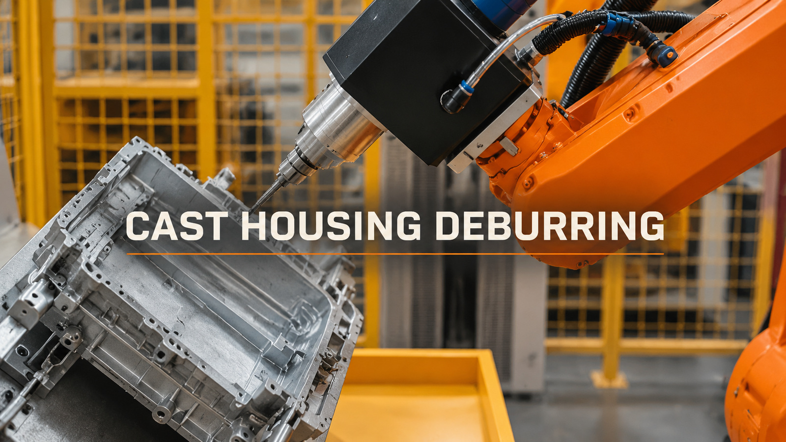
Define what must be removed and what must remain before tuning a robot’s deburring path. Flash, an allowed edge break and a protected sealing or mating surface require different acceptance decisions. A smooth demonstration part can conceal the more important question: will the process remove the permitted variation in burrs without taking unacceptable material from the housing?
Start with the edge that must survive
Mark the removal region on the housing drawing or sample. Separately identify functional faces, permitted edge changes and features that must not be touched. “No burrs” is incomplete if the inspection method cannot also detect an edge that has been cut back too far.
Keep representative incoming parts, including the variations that make manual deburring difficult. Compare the location and extent of the unwanted material with the locating surfaces used by the fixture. This helps distinguish a changing burr from a housing that sits in a different position.
The process footage shows a robot carrying a slender tool along local edges of an aluminum cast housing. The fixture turns the housing and the tool continues processing another face. For a comparable application, the edge definition should therefore remain clear after the part changes orientation, not only at the easiest visible side.
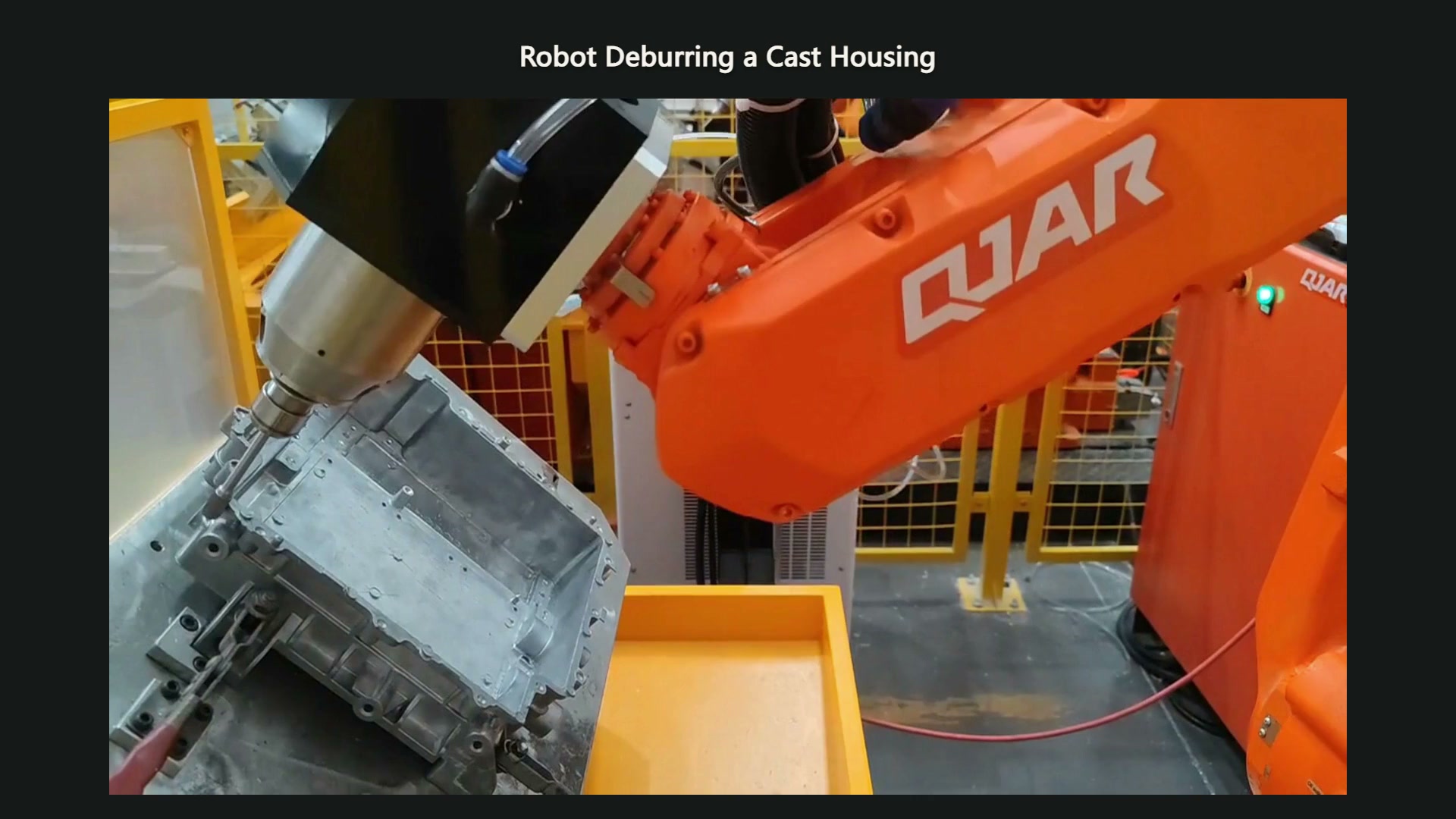
00:09 — The tool is at a local edge of the housing in its first orientation.
A repeated route can produce different contact
The programmed route describes nominal tool motion. It does not, by itself, establish where every production edge meets the cutter. A shifted casting, variation in the parting line or a changed tool can alter the contact even when the robot repeats its command.
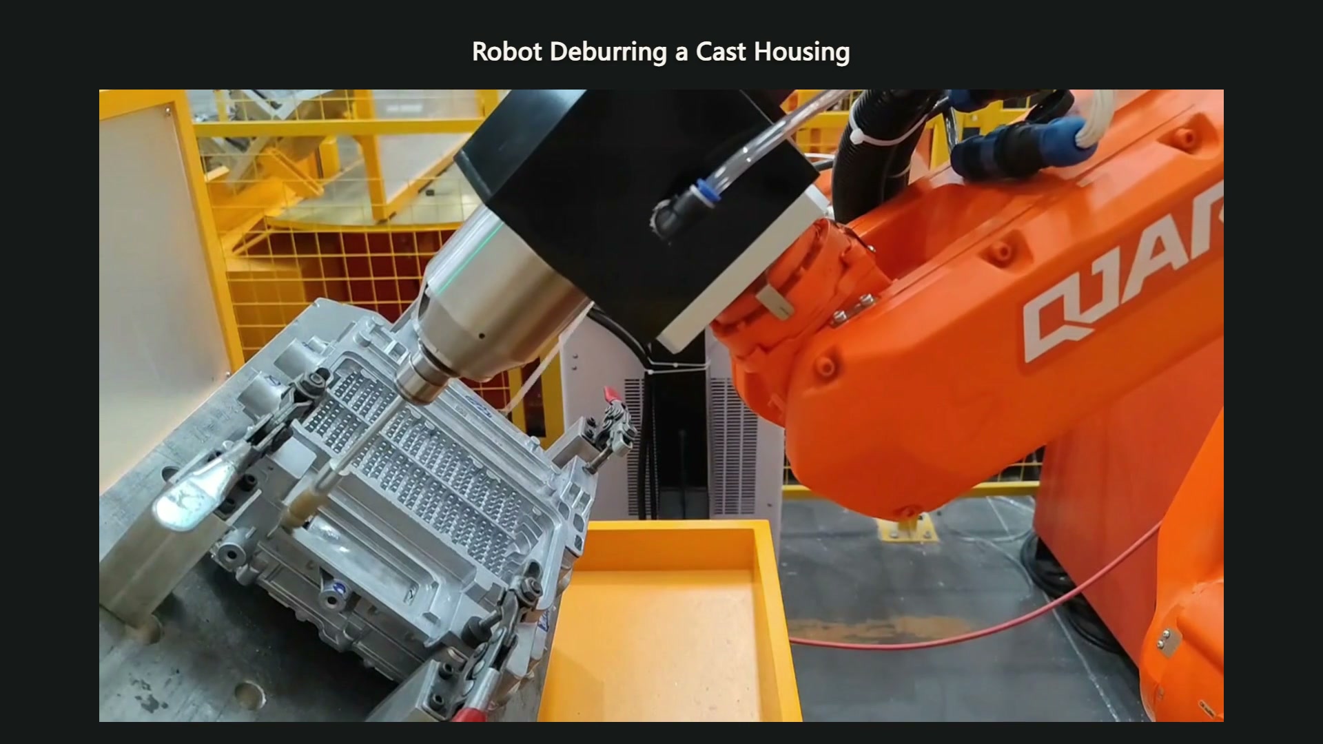
00:36 — The fixture has turned the housing, exposing another face near the tool.
Separate the observations before correcting the program:
| Παρατήρηση δοκιμής | What the comparison should help separate |
|---|---|
| A residual burr moves with the casting’s position | Variation in location or support versus an unsuitable nominal path |
| More material remains where incoming flash is larger | Variation in removal demand versus the chosen cutting conditions |
| A clean edge is accompanied by damage to a functional face | Contact direction, access and allowed removal boundary |
| Results change over a tool’s service interval | Tool condition versus a change in incoming parts or setup |
These are diagnostic possibilities for a proposed trial. Retain the before-and-after samples so a path change is judged against both burr removal and preservation of the housing.
Compliance has a direction and a job
Original tool documentation describes radial compliance for following deviations around an edge profile, while axial floating tools accommodate contact in another direction. Choosing between them requires understanding how the intended cutter meets the surface. “Floating tool” is not a complete process specification.
A compliant mechanism can accommodate the displacement it is designed for; it does not define the permitted edge or correct an unsuitable locating strategy. Nor does its presence establish that a large, variable flash can be removed in one pass. Those questions still require the actual material and burr condition.
One original pneumatic deburring-tool manual treats compliance force and robot traverse speed as separate adjustments used to obtain the required cut and finish. The useful lesson is to evaluate contact conditions together. Increasing force to remove a stubborn burr can change the cut on a thinner neighbouring edge; a successful adjustment must be checked on both conditions. The tool maker’s ratings remain specific to its equipment.
Accept a production range, not a polished sample
Run the intended locating and face-change sequence with the agreed range of castings. Inspect the protected areas as well as the cleared edge. Include the proposed tool-maintenance or replacement condition in the trial so the acceptance does not rely on an unexplained fresh-tool result.
Record which incoming burr conditions the process accepts, which need a different operation and how the edge is judged. A boundary expressed in drawings, samples and an agreed inspection method is more useful than a promise that the robot follows the same path every time.
For an application discussion, bring EVST actual burred parts, good and rejected examples, and marked functional surfaces. The next step is to discuss a testable removal boundary and the sample variation that the proposed process must cover.