
By Συντακτική Ομάδα EVST · Αξιολογήθηκε από Συντακτική Ομάδα EVST · Τελευταία ενημέρωση 10 Οκτωβρίου 2026 · Εκδοτική πολιτική · Διορθωτική πολιτική · Όροι
A long sheet-metal argon-arc seam remains controllable when the joint and fixture hold a repeatable line, the ceramic nozzle and side-fed wire keep a suitable relationship to the weld pool, and the seam end has a planned arc-ending method. These three conditions must be checked together: joint movement changes torch alignment, torch alignment changes where wire enters the pool, and the final approach determines what can be done at the end.
Send your sheet-metal drawing and daily output, and we will prepare an automation concept and cycle-time estimate. Include the joint section, fixture arrangement and required weld acceptance criteria.
One seam is enough to expose the real coordination problem
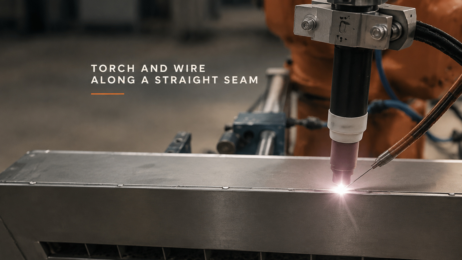
The documented sequence shows one continuous straight seam on a long sheet-metal part. A ceramic nozzle points toward the joint while a side guide feeds wire to the front of the bright weld pool. The torch advances along the same line; the part and fixture remain in position. The relationship stays visible through the middle of the seam and as the torch approaches the part end.
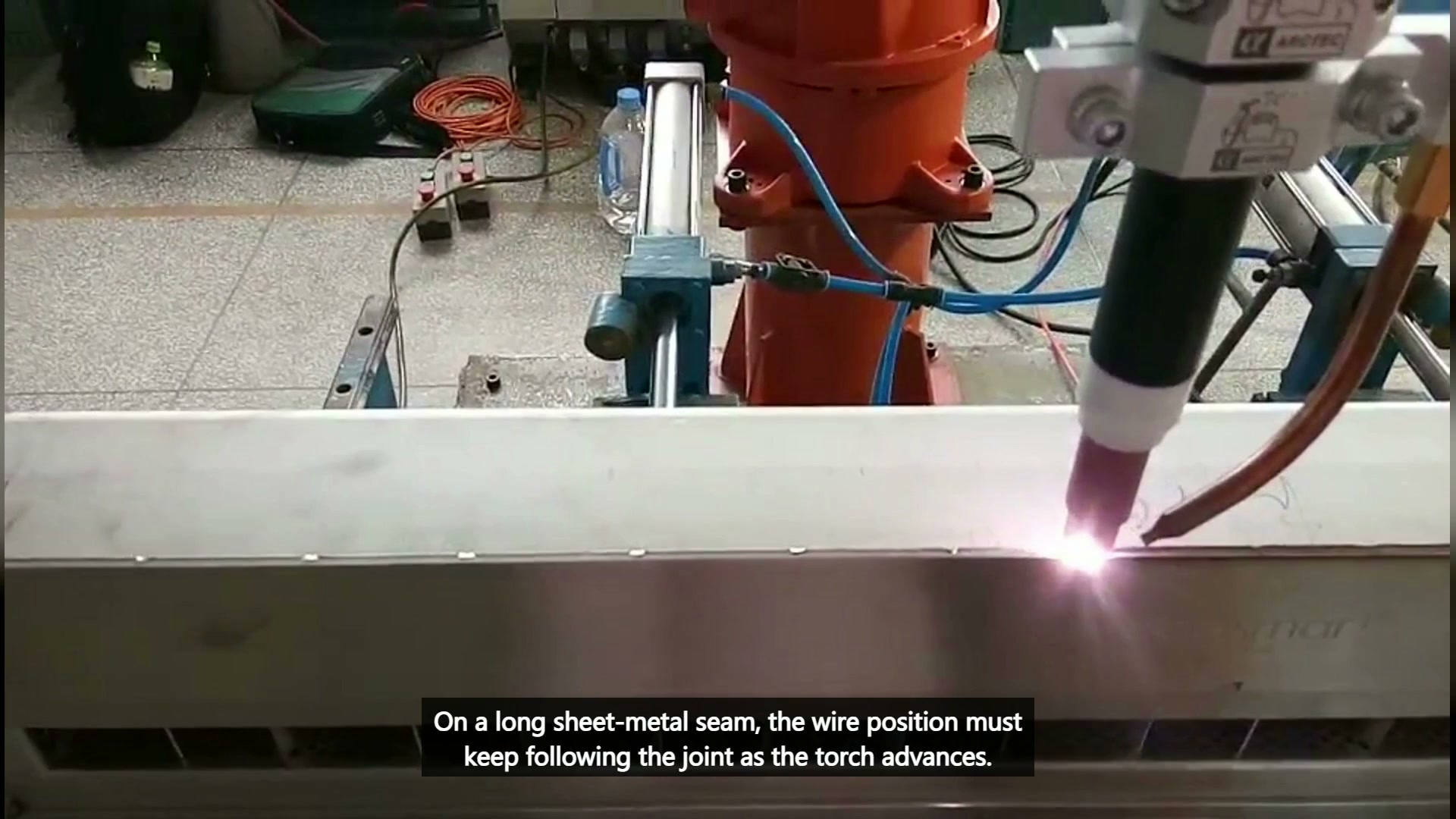
This narrow view is useful because it removes unrelated claims. It does not show loading, another seam, a weaving path or a verified arc-ending result. The engineering question is how to preserve the working relationship along the one seam that is visible.
The fixture establishes the line the torch must follow
Robot repeatability cannot correct a joint that changes position unpredictably. Before programming the path, define how the two sheet-metal edges locate, where clamps act and whether the joint line remains accessible. Supports should hold the part without placing clamp hardware in the torch, wire-guide or robot path.
Check the start, middle and end of the joint against the fixture datum. A long part can magnify small placement or forming differences. If the joint position varies, the project needs a defined way to manage that variation; this footage does not establish vision tracking or automatic seam finding.
The fixture also affects heat response, but deformation and weld quality cannot be read from the video. Those outcomes require the actual sheet geometry, joint preparation, clamping plan and qualified process parameters.
Torch and side-fed wire form one moving geometry
With side-fed wire, the wire guide is not a separate accessory to position later. The ceramic nozzle, wire tip, joint and pool form one geometry that must remain suitable as the robot moves. Changing torch angle changes where the wire reaches the pool; changing the wire-guide angle can reduce access or create interference near the fixture.
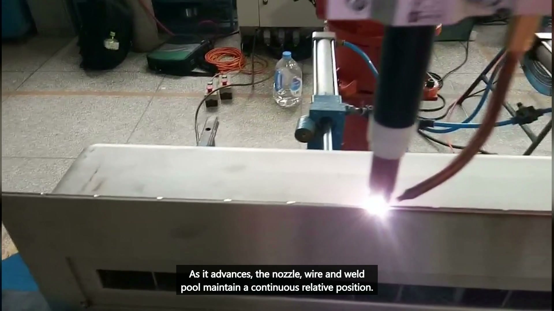
Define the intended torch angle and wire entry relationship from the weld procedure, then model both bodies through the full seam. Include the guide, brackets, hoses and cable routing in the clearance check. At the middle of a long straight joint, the posture may look simple; at the start or end, nearby fixture hardware can limit the same relationship.
The path should be smooth enough that the relative geometry does not change through unnecessary wrist motion. This does not mean the torch must have one universal angle for every product. It means each approved joint condition needs a deliberate, repeatable relationship.
Treat the seam end as a planned process zone
The final usable footage shows welding continuing as the torch approaches the end of the long part. It does not show a separate, verified arc-ending result. A production plan should therefore define the end condition before commissioning rather than infer it from the recording.
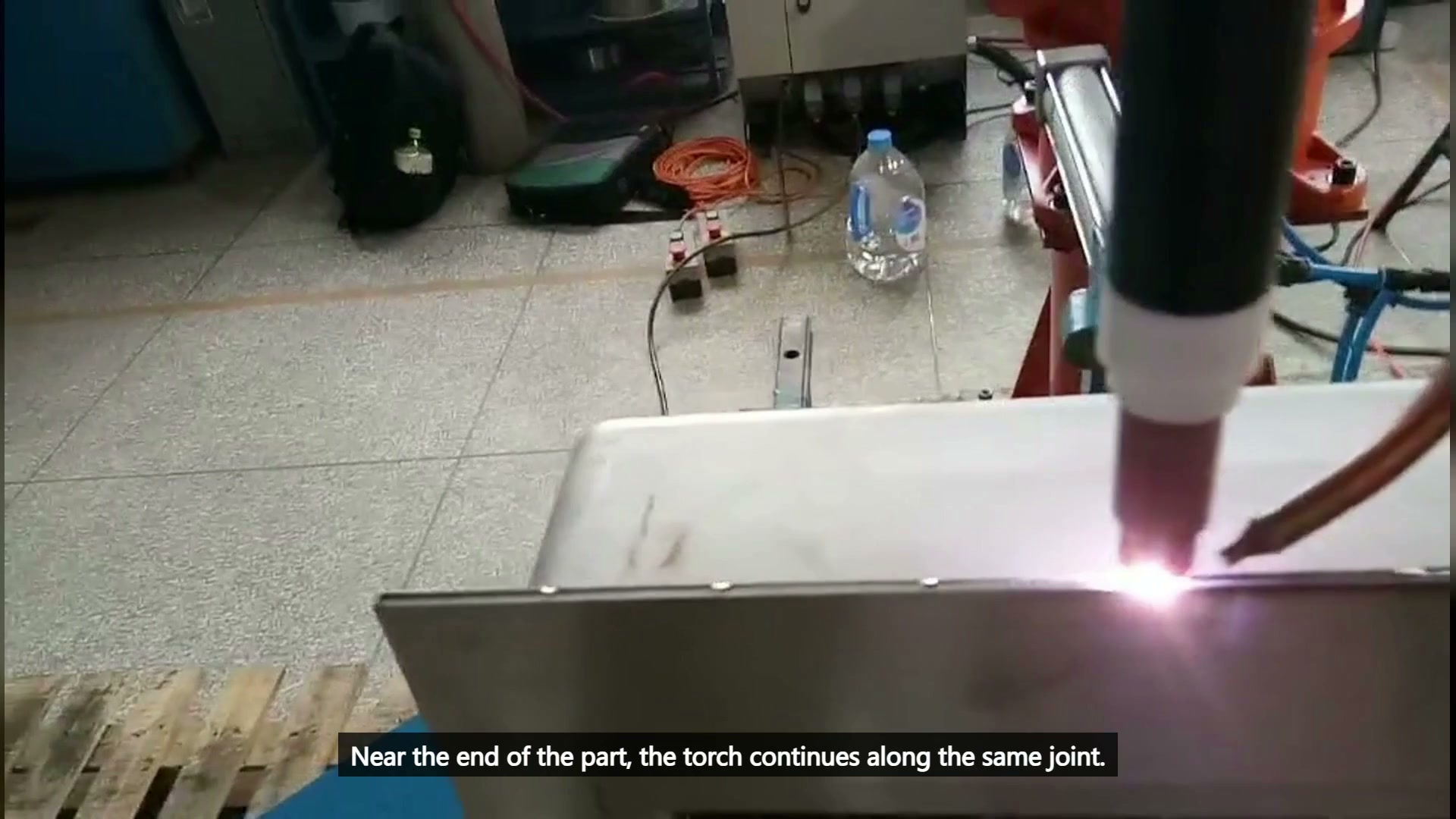
The project inputs should state where the effective seam ends, whether run-on or run-off provisions are allowed, and what weld termination the drawing requires. The robot path, wire feed and arc sequence must support that requirement. Final values for current, voltage, gas flow, wire, speed and timing come from the approved welding procedure and trials, not from visible motion.
A three-zone validation plan
| Ζώνη | Κύρια ερώτηση | Απαιτούμενα αποδεικτικά στοιχεία |
|---|---|---|
| Αρχική | Can the torch and wire establish the approved relationship without fixture interference? | Joint start geometry and fixture model |
| Μέσο | Does the straight path preserve joint, nozzle, wire and pool alignment? | Representative part variation and path trial |
| Τέλος | Can the specified weld termination be executed within the available space? | Drawing requirement and end-feature geometry |
Validate all three zones on the actual part. A good middle section cannot compensate for a blocked start or an undefined end.
Procurement should separate the robot package from the process inputs the plant supplies. The integrator can design the fixture, path and access study, while the buyer defines acceptable joint variation, the approved welding procedure and inspection method. A useful quotation binds the proposed cell to the actual part range and acceptance basis rather than one nominal seam.
For a trial, use parts representing the expected forming range. Record joint position at the start, middle and end, then compare those measurements with the fixture datum and weld inspection. This distinguishes incoming-part, clamping, access and process issues.
Questions buyers ask about long straight seams
Does a straight joint need seam tracking?
Not automatically. First quantify how much the joint position varies after forming and fixturing. If variation exceeds what the qualified process can accept, evaluate a suitable correction method. This cell does not prove one is present.
Can the side wire guide stay fixed relative to the torch?
It can when that relationship gives the required wire entry and clears the fixture throughout the seam. Check the complete assembly at the start, middle and end.
Does the visible seam prove the final weld result?
No. The footage shows continuous travel, the ceramic nozzle, side-fed wire and pool. Weld penetration, deformation and acceptance require procedure data and inspection.
Τι να στείλετε για μια μηχανική αξιολόγηση
Send the sheet-metal drawing, daily output, joint section, seam length, edge preparation, fixture concept and weld acceptance criteria. Include the existing welding procedure if one is approved, plus the available start and end space around the joint.
With those inputs, we can review fixturing, torch and wire access, path zones and a trial plan. Discuss your long-seam welding application with EVST ή e-mail sales@evsrobot.com with your drawing and daily output for an automation concept and cycle-time estimate.
This article covers one visible continuous straight seam and general planning principles; it does not state current, voltage, gas flow, wire material, speed, penetration, deformation, quality result or cycle time for this cell.