
Robot tending a press should be planned as two handoffs, not as one robot motion. The first handoff is at the nearby conveyor area; the second is at the die area inside the press station. Before programming a production path, define the part state at each handoff and confirm that the end tool has room to approach, grip or release, and withdraw.
The video shows an orange industrial robot repeatedly moving its end tool into the die area on the press table and turning toward a small conveyor area at the left front of the cell. Use this visible relationship to define the two handoffs before path programming. For a project review, óska eftir tilvitnun or email sales@evsrobot.com with the press layout, die opening, workpiece information, and transfer-area drawing.
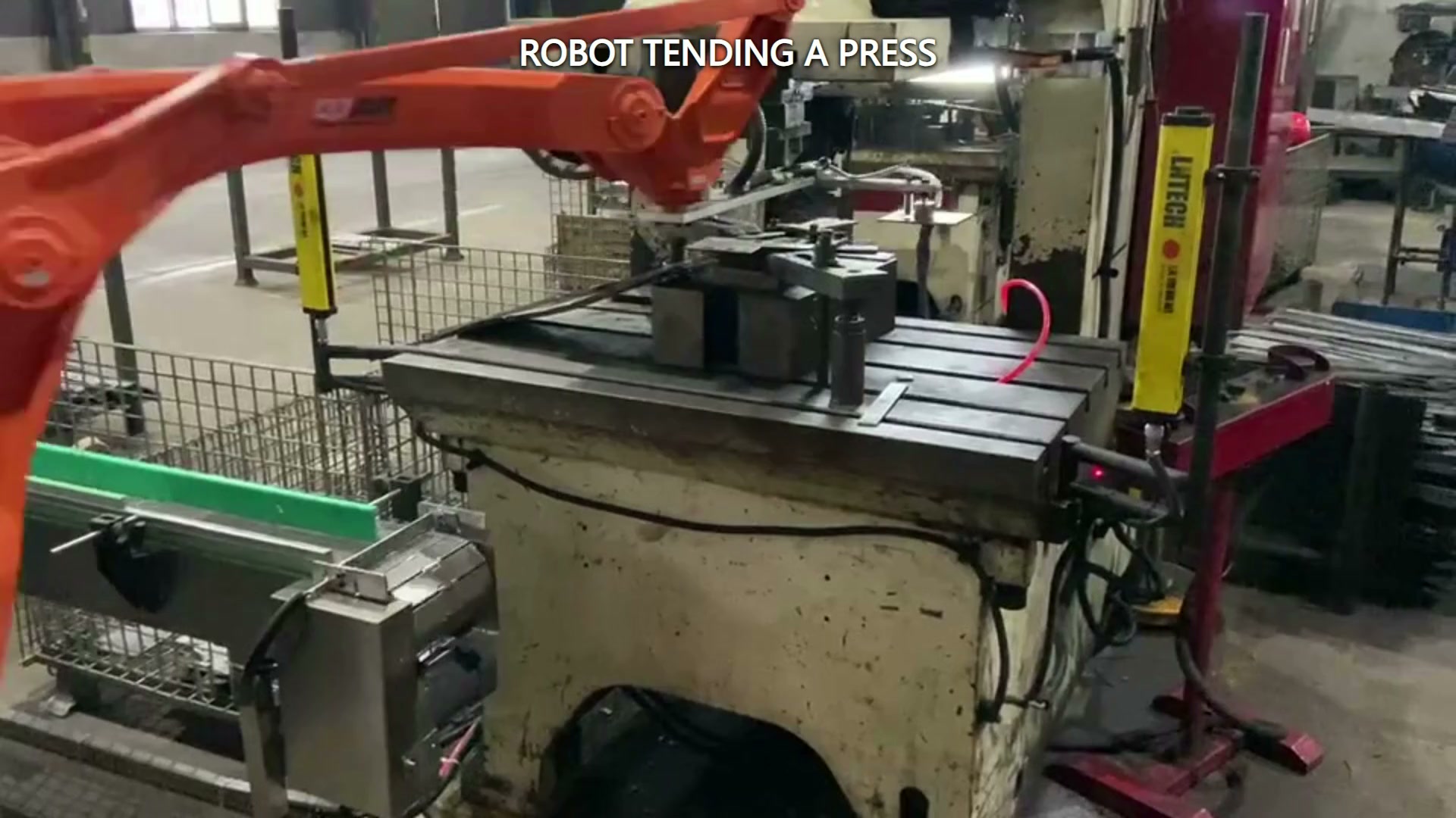
Treat the cell as two handoff problems
A reach study can show that a robot can place its tool near both locations. The next check uses the carried-workpiece envelope, accessible gripping interface, and post-release withdrawal path. The useful design question is therefore not simply “Can the robot reach?” It is “Can the complete tool-and-workpiece envelope complete both handoffs without creating an unresolved interference or recovery problem?”
At the conveyor-side handoff, establish the expected workpiece pose, the surface available for gripping, and the space around guides, stops, neighbouring pieces, and the conveyor frame. The approach direction should tolerate the pose variation expected from the feeding method. Record any required sensing or mechanical location in the project specification and acceptance plan.
At the die-side handoff, examine the opening around the tool or die, the support surface, and the direction in which the end tool must retreat. A tool may reach the nominal placement point yet lack room to open, release, rotate, or withdraw. This is why a die-area layout review must include the end tool body, wrist, hoses or cables, and the workpiece envelope rather than the robot centreline alone.
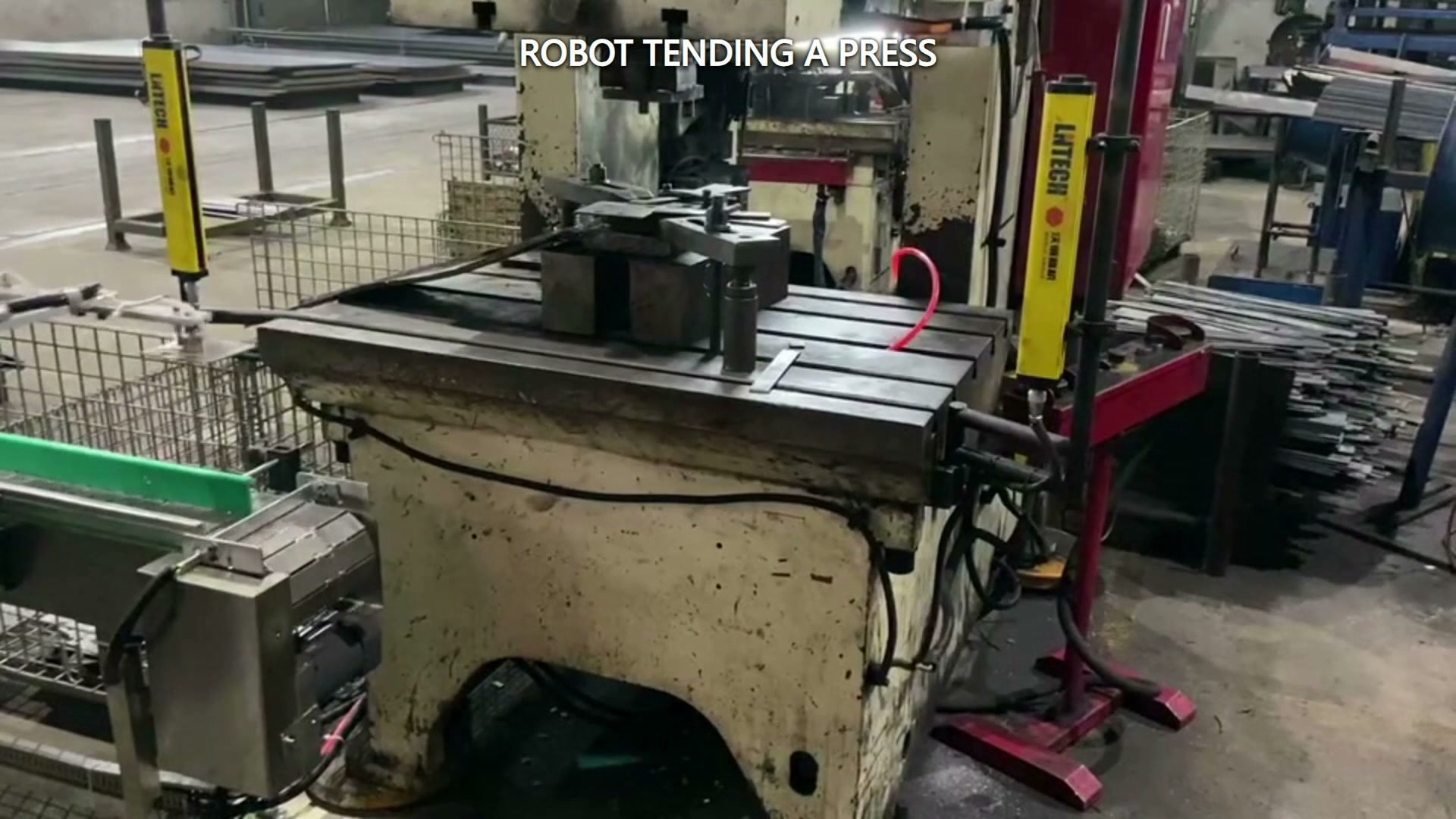
Use a three-space clearance check
The following check separates three kinds of space that are often compressed into one reach question.
| Space to verify | Hvað á að endurskoða | A failure may look like |
|---|---|---|
| Approach space | Tool, wrist and workpiece envelope while entering the handoff | The robot reaches the target only with an impractical wrist angle or interference risk |
| Grip or release space | Jaw, pad or other contact interface at the handoff | The tool reaches the location but cannot close, seat, open or release cleanly |
| Exit space | Tool withdrawal after pickup or release | The workpiece is placed, but the empty tool cannot leave along a clear path |
Keep process logic separate from visible motion
The repeated travel between the press table and the nearby conveyor area is useful for explaining the physical relationship between stations. Control logic still needs its own definition. A project team would normally identify the states that permit entry, pickup or placement, withdrawal, and the next machine action. It would also define what happens when the expected part state is absent, the tool does not confirm its state, or a workpiece cannot be released.
Writing these states before simulation gives controls, tooling, and process teams one common handoff definition. Each state can then be verified against the actual press, tooling, workpiece, operating method, and recovery plan.
Evaluate the complete application boundary
Official press-safety guidance treats the press, tooling or dies, safeguarding, material handling, workpiece configuration, and production requirements as an integrated system. Industrial robot integration guidance likewise addresses the robot application and cell rather than the arm in isolation. For a feasibility review, the practical boundary therefore includes the robot, end tool, press, die area, conveyor, controls, safeguarding, access for setup, and access for clearing abnormal conditions.
A project risk assessment should cover the complete application boundary and every relevant operating mode, including setup, changeover, clearing, and maintenance access.
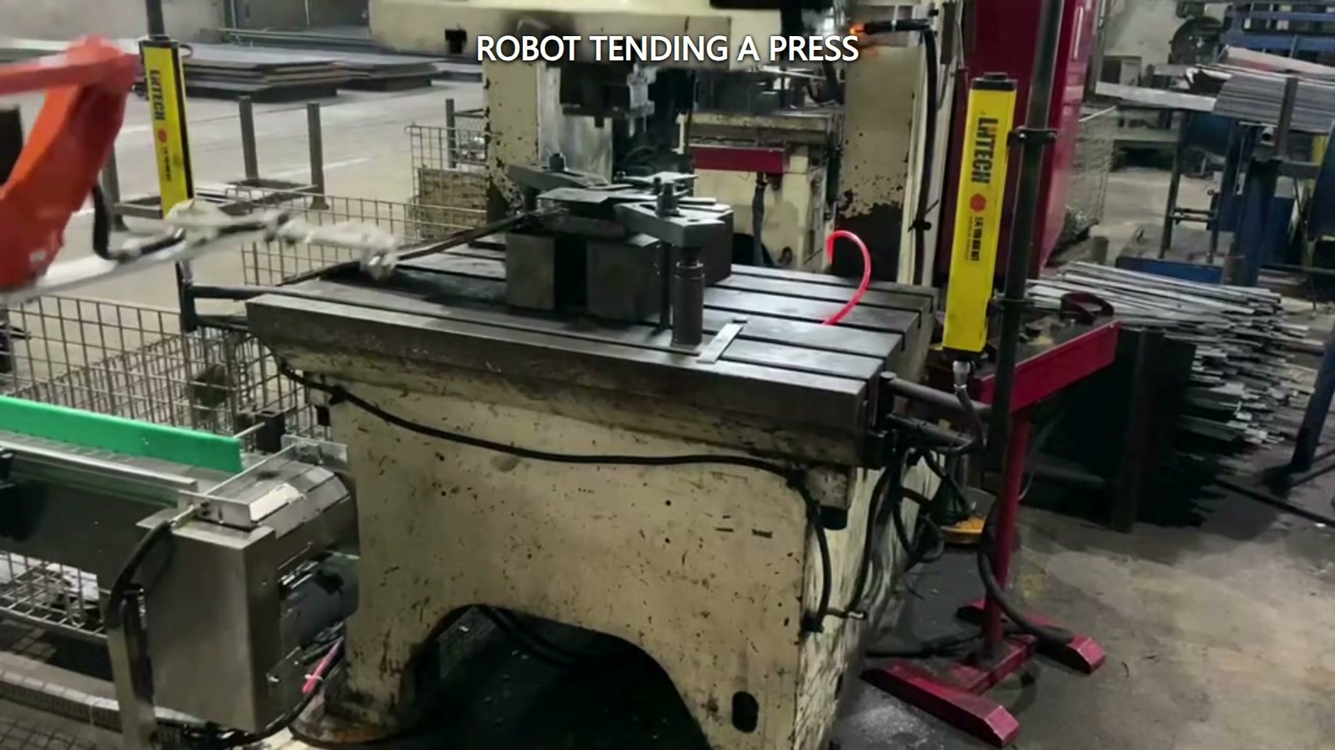
Inputs for a useful feasibility review
Provide the following before committing to a robot path:
- workpiece drawings, mass properties, allowed contact surfaces, and acceptable orientation range;
- die-area opening, support surfaces, and permitted approach and withdrawal directions;
- conveyor handoff position, guides, stops, spacing, and expected pose variation;
- end-tool concept, required opening or release motion, and the full tool-and-workpiece envelope;
- press states and interface signals available to the integrated cell;
- changeover method, abnormal-part handling, setup access, maintenance access, and recovery procedure;
- the project risk assessment and the safeguarding concept for every relevant operating mode.
With these inputs, simulation and physical trials can test the two handoffs as bounded tasks. The acceptance method should check representative workpiece states and recovery cases, not only one clean demonstration cycle.
Turn the handoff review into a project brief
Mark the conveyor pickup envelope and die-area placement envelope on one layout, then attach the workpiece and end-tool information listed above. This gives the project team a concrete basis for simulation, tooling review, controls definition, and representative trials. Request an engineering quote or email sales@evsrobot.com.
The footage supports only the visible robot movement between the die area and nearby conveyor area; part identity, exact transfer sequence, controls, safety and production results require project evidence.